22 PL12EN-1001 2011-04 en02d441_bedingt.fm, 07.04.2011
Controller specifications
2
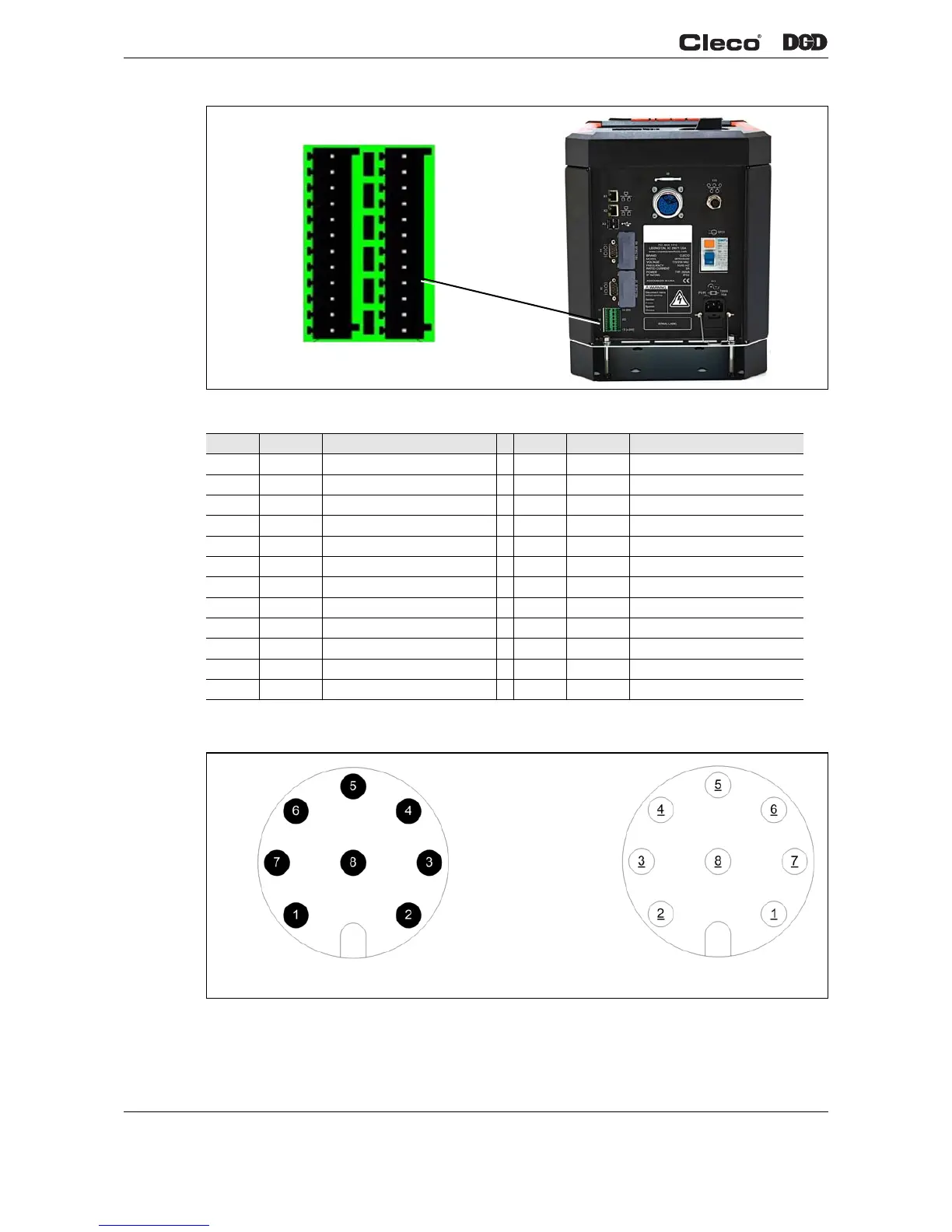
Fig. 2-4 Primary / Master Pin Configuration
System Bus Connection
Fig. 2-5 System Bus Connection
Pin # I/O Description Pin # I/O Description
12 Out GND2 24 Out GND2
11 In Common GND 23 In Common GND
10 Output O 03 22 Output O 07
9 Output O 02 21 Output O 06
8 Output O 01 20 Output O 05
7 Output O 00 19 Output O 04
6 Input I 03 18 Input I 07
5 Input I 02 17 Input I 06
4 Input I 01 16 Input I 05
3 Input I 00 15 Input I 04
2 In Output Common O0-O3 14 In Output Common O4-O7
1 Out +24 V2 13 Out +24 V2
d01223_1.png
Pin 1
Pin 13
Pin 24
Pin 12
Looking at
Controller
1 – PE
2 – DATA-B
3 – GND
4 – +5VDC
5 – DATA-A
6 – N.C.
7 – 0VDC
8 – +24VDC
Input (Pins)
Output (Sockets)
 Loading...