en02d441_bedingt.fm, 07.04.2011 PL12EN-1001 2011-04 23
Controller specifications
2
Note: The Primary configuration has an output connector only. The Secondary and Master configurations
have both an input and output connector.
AC power supply
• 104–126 VAC or 207–253 VAC
• 50–60 Hz single phase
• 1 A Input current (rated), 16 A (peak)
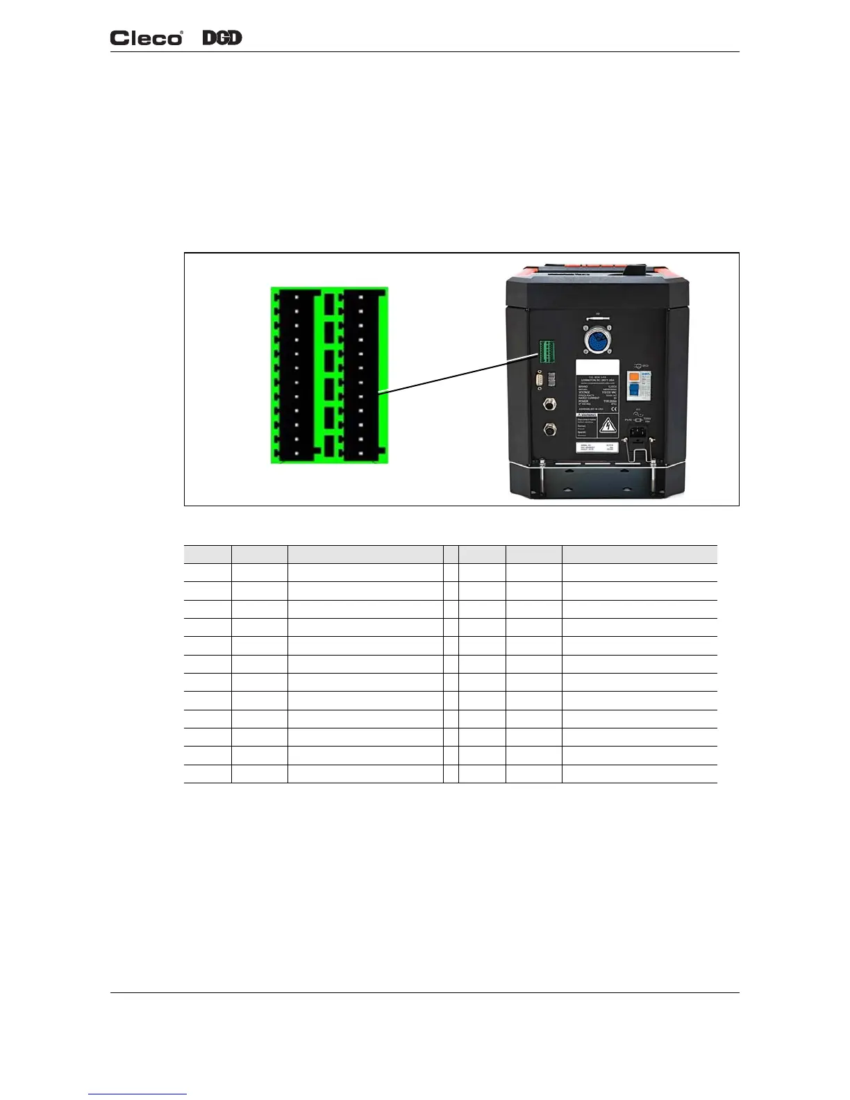
2.1.3 Secondary Configuration
Fig. 2-6 Secondary Pin Configuration
Serial Port
• RS232
• System Bus Connectors
- 1 Male
- 1 Female
Pin # I/O Description Pin # I/O Description
12 Out Common GND2 24 Out Common GND
11 In Common GND 23 In Common GND
10 Output O 03 22 Output O 07
9 Output O 02 (Yellow LED) 21 Output O 06
8 Output O 01 (Green LED – OK) 20 Output O 05
7 Output O 00 (Red LED – NOK) 19 Output O 04
6 Input I 03 18 Input I 07
5 Input I 02 17 Input I 06
4 Input I 01 (Reverse) 16 Input I 05
3 Input I 00 (Start) 15 Input I 04
2 N. C. 14 N. C.
1 Out +24 VDC 13 Out +24 VDC
d01223_2.png
Pin 1
Pin 13
Pin 24
Pin 12
 Loading...