Apex Tool Group P2309HW | 2018-09 11
1
EN
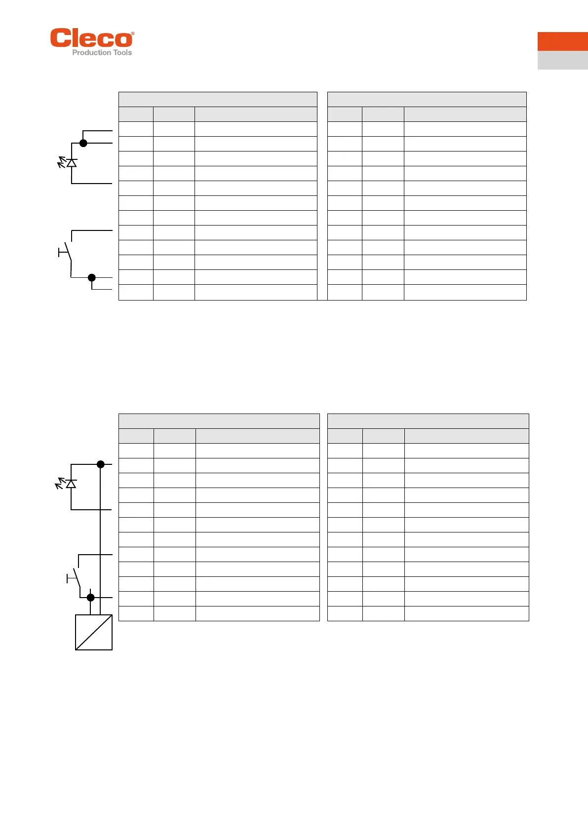
Connectors – Internal power supply
Example:
Inputs
• Internal 24 V power supply for the controller.
• Pin 11 and 23 (common GND) serve as a "return line"
for the outputs.
• Pin 11 and 23 must be connected to Pin 12 or 24 with
jumpers.
Outputs
• Internal 24 V power supply for the controller
• Pin 2 and 14 (common output) are the voltage source
for the inputs.
• Pin 2 and 14 must be connected to Pin 1 or 13
Connectors – external power supply
Example:
Inputs
• External 24 V power supply for the controller.
• Pin 11 and 23 (common GND) serve as a "return line"
for the outputs.
• The GND for the external 24 V power supply must be
used as the return line for Pin 11 and 23.
Outputs
• External 24 V power supply for the controller.
• Pin 2 and 14 (common output) are the voltage source
for the inputs.
• Pin 2 and 14 must be connected to the external 24 V
power supply.
Signal X9 Signal X10
Pin I/O Name Pin I/O Name
12 Supply GND Int. 24 Supply GND Int.
11 Supply GND I/O 23 Supply GND I/O
10 Output O3 22 Output O7
9 Output O2 21 Output O6
8 Output O1 20 Output O5
7 Output O0 19 Output O4
6 Input I3 18 Input I7
5 Input I2 17 Input I6
4 Input I1 16 Input I5
3 Input I0 15 Input I4
2 Supply +24 V O 14 Supply +24 V O
1 Supply +24 V Int. 13 Supply +24 V Int.
Signal X9 Signal X10
Pin I/O Name Pin I/O Name
12 Supply GND Int. 24 Supply GND Int.
11 Supply GND I/O 23 Supply GND I/O
10 Output O3 22 Output O3
9 Output O2 21 Output O2
8 Output O1 20 Output O1
7 Output O0 (linking OK), e.g. 19 Output O0 (linking OK), e.g.
6 Input I3 (tool start), e.g. 18 Input I3 (tool start), e.g.
5 Input I2 17 Input I2
4 Input I1 16 Input I1
3 Input I0 15 Input I0
2 Supply +24 V O 14 Supply +24 V O
1 Supply +24 V Int. 13 Supply +24 V Int.
+
-