10 P2309HW | 2018-09 Apex Tool Group
1
EN
5 Pin Assignment
This chapter describes the Cleco Production Tools specific
connectors. Standard plugs are not considered. All con-
nections are short-circuit proof.
X5, X6 – Serial port for additional devices
• All outputs provide RS232 conforming signals.
• The inputs allow voltages in the range from -15 V to
+15 V.
- Voltages < 0.8 V correspond to a zero.
- Voltages > 2.4 V are interpreted as a one.
- Open inputs are preset to zero using a pulldown
resistor.
• The power supply pins are connected directly to the
main board power supply
.
X7, X8 – Anybus CC
Optional slots for Anybus CC modules.
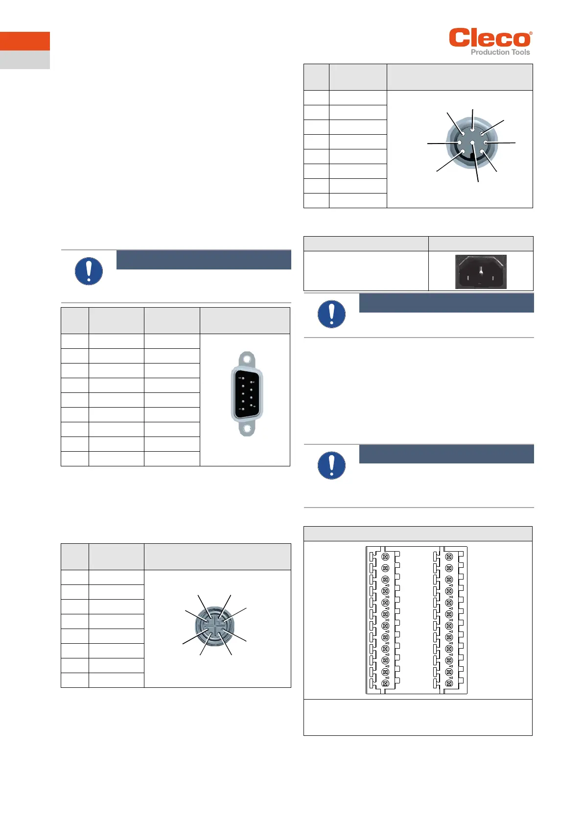
X21 – TSnet System Bus Out
Interface port for TSnet cable.
X22 – ARCNET System Bus
The station controller has an integrated bus termination;
therefore, no external termination is necessary.
X23 – Supply
X9, X10 – Input/Output
The required signal circuits are connected to these input/
output connectors. The signal groups are not galvanically
connected to the power supply; galvanic isolation is
required.
• 8 inputs/8 outputs, optically isolated for 24 V level/
0.5 A
• Output current: 500 mA per output, 2000 mA total
Note
Do not connect or disconnect any device
during operation. Doing so may result in a
system reset.
Pin X5
RS232-1
X6
RS23-2
9 Pin D-Sub Male
with Screw Lock
1 – –
2 RxD RxD
3 TxD TxD
4 – –
5 GND GND
6 – –
7 RTS RTS
8 CTS CTS
9 – –
Pin Signal 8 Pin M12 Circular Connector
X-Coded
1 Tx +
2 Tx -
3 Rx +
4 RX -
5 0 VDC
6 0 VDC
7 +24 VDC
8 +24 VDC
2
1
8
7
6
5
4
3
Pin Signal 8 Pin M12 Circular Connector
A-Coded
1 N.C.
2 DATA-B
3 GND
4 +5 VDC
5 DATA-A
6 N.C.
7 0 VDC
8 +24 VDC
Description IEC Connector C14
Connector with Fuse Holder
2-Pin, 5 × 20 mm, 16 A
Slow-Blow
Note
Use plug locking mechanism.
See Quick Installation Guide.
Note
A single device must not require a current of
more than 500 mA. The current monitor
switches off the output in the event of an
overcurrent.
2x12 Pin Phoenix MCD 0.5/24-G1-2.5
Mating Connector
Phoenix FK-MC 0.5/12-STZ3-2.5
Order no. S981211
Output (Sockel)
6
7
8
2
3
4
5
1
X9
X10