Schematic Diagrams
B-1
B.Schematic Diagrams
Appendix B: Schematic Diagrams
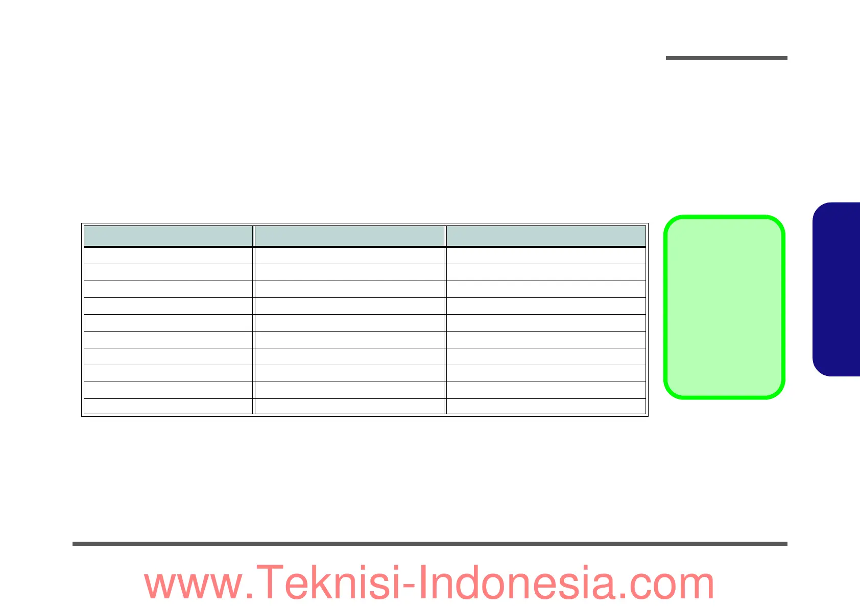
This appendix has circuit diagrams of the W210CUQ, W211CU, W215CU notebook’s PCB’s. The following table indi-
cates where to find the appropriate schematic diagram.
Diagram - Page Diagram - Page Diagram - Page
System Block Diagram - Page B - 2 Tigerpoint Part E-F - Page B - 12 PWR SW, 1.8VS, 3VS, 5VS, 1.5VS - Page B - 22
Cedarview CPU Part D - Page B - 3 Panel, HDD, LED - Page B - 13 PWR VCORE - Page B - 23
Cedarview CPU Part A-C-F - Page B - 4 BTB, 3G, WLAN, BT - Page B - 14 PWR VDD3, 3.3V, VDD5V, SYS15V - Page B - 24
Cedarview CPU Part B - Page B - 5 Audio Codec VT1812P - Page B - 15 CRT - Page B - 25
Cedarview CPU Part E - Page B - 6 KBC-ITE IT8502E-J, TP, LID - Page B - 16 Card Reader (w/ LAN) JMB261C - Page B - 26
DDRIII SO-DIMM_0 - Page B - 7 TPM & HDMI - Page B - 17 BTB, USB, CCD, PWR SW - Page B - 27
IDT CLOCK - Page B - 8 USB PORT & USB CHARGER - Page B - 18 Click Board - Page B - 28
Tigerpoint Part A-B - Page B - 9 PWR AC IN, CHARGE - Page B - 19 Power Button Board - Page B - 29
Tigerpoint Part C - Page B - 10 PWR 1.5V, 0.75V - Page B - 20 Power Button for M1115 - Page B - 30
Tigerpoint Part D - Page B - 11 PWR 1.05VS - Page B - 21
Table B - 1
SCHEMATIC
DIAGRAMS
Version Note
The schematic diagrams
in this chapter are based
upon version 6-7P-
W2105-001. If your main-
board (or other boards)
are a later version, please
check with the Service
Center for updated dia-
grams (if required).
www.Teknisi-Indonesia.com
 Loading...