11
Tranquility
®
Digital Air Handler (TAH)
Rev.: 11 Feb., 2013
CAUTION!
CAUTION! Installation of a factory supplied liquid line
bi-directional fi lter drier is required. Never install a suction
line fi lter in the liquid line.
CAUTION!
See compressor section IOM for refrigerant charge
information.
Line Set Installation
Figure 5 illustrates a typical installations of an air handler or
cased coil matched to an indoor compressor section. Table
A shows typical line-set diameters at various lengths. Lineset
lengths should be kept to a minimum and should always be
installed with care to avoid kinking. Line sets over 60 feet [18
meters] long are not recommended due to potential oil transport
problems and excessive pressure drop. If the line set is kinked
or distorted, and it cannot be formed back into its original
shape, the damaged portion of the line should be replaced. A
restricted line set will effect the performance of the system.
All brazing should be performed using nitrogen circulating
at 2-3 psi [13.8-20.7 kPa] to prevent oxidation inside the
tubing. All linesets should be insulated with a minimum
of 1/2” [13mm] thick closed cell insulation. All insulation
tubing should be sealed using a UV resistant paint or
covering to prevent deterioration from sunlight.
When passing refrigerant lines through a wall, seal
opening with silicon-based caulk. Avoid direct contact
with water pipes, duct work, fl oor joists, wall studs,
fl oors or other structural components that could transmit
compressor vibration. Do not suspend refrigerant tubing
from joists with rigid straps. Do not attach line set to the
wall. When necessary, use hanger straps with isolation
sleeves to minimize transmission of line set vibration to
the structure.
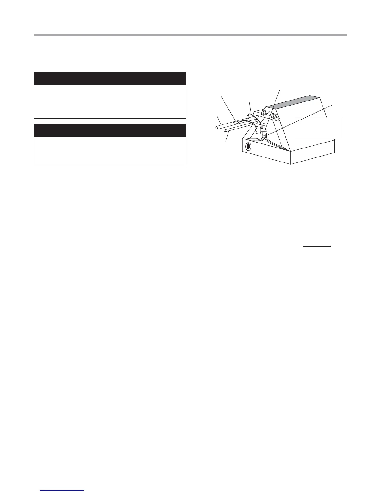
Installing the Indoor Coil and Lineset
Figure 3 shows the installation of the lineset and TXV to
a typical indoor coil. Braze the copper line set to the coil.
Nitrogen should be circulated through the system at 2-3 psi
[13.8-20.7 kPa] to prevent oxidation inside the refrigerant
tubing. Use a low silver phos-copper braze alloy on all brazed
connections.
Installation
Figure 3: Air Coil Connection
NOTICE! The air coil should be thoroughly washed with a
fi lming agent, (dishwasher detergent like Cascade) to help
condensate drainage. Apply a 20 to 1 solution of detergent
and water. Spray both sides of coil, repeat and rinse
thoroughly with water. Care should be taken not to overfl ow
drain pan. Wash after connecting condensate line.
Sensing Bulb
IMPORTANT: DO NOT perform any brazing with the TXV
bulb attached to any line. After brazing operations have been
completed, clamp the TXV bulb securely on the suction line
at the 10 or 2 o’clock position with the strap provided in the
parts bag. Insulate the TXV sensing bulb and suction line
with the provided pressure sensitive insulation (size 4” x 7”).
IMPORTANT: TXV sensing bulb should be located on a
horizontal section of suction line, just outside of coil box.
IMPORTANT: Always protect TXV from heat when brazing.
IMPORTANT: TXV sensing bulb is shipped unattached.
Installer must attach bulb to suction line after brazing and
cooling line for proper unit operation.
CAUTION! HFC-410A systems operate at higher
pressures than R-22 systems. Be certain that service
equipment (gauges, tools, etc.) is rated for HFC-410A.
Some R-22 service equipment may not be acceptable.
TXV (‘IN’ toward
compressor section)
Suction Line
Liquid Line
Bulb (Must be
Installed and
Insulated)
Equalizer
Line
TXV has internal
check valve
LT2
Sensor