Tranquility
®
Digital Air Handler (TAH)
Rev.: 11 Feb., 2013
12
Geothermal Heat Pump Systems
Evacuation and Charging the Unit
LEAK TESTING -
The refrigeration line set must be pressurized
and checked for leaks before evacuating and charging the unit.
To pressurize the line set, attach refrigerant gauges to the service
ports and add an inert gas (nitrogen or dry carbon dioxide) until
pressure reaches 60-90 psig [413-620 kPa]. Never use oxygen
or acetylene to pressure test. Use a good quality bubble solution
to detect leaks on all connections made in the fi eld. Check the
service valve ports and stem for leaks. If a leak is found, repair it
and repeat the above steps. For safety reasons do not pressurize
system above 150 psig [1034 kPa]. System is now ready for
evacuation and charging.
Condensate Drain Tubing
Consult local codes or ordinances for specifi c requirements.
IMPORTANT: When making drain fi tting connections to the
drain pan, use a thin layer of Tefl on paste, silicone or Tefl on
tape and install hand tight.
IMPORTANT: When making drain fi tting connections to drain
pan, do not overtighten. Overtightening fi ttings can split pipe
connections on the drain pan.
• Install drain lines so they do not block service access
to front of the unit. Minimum clearance of 24 inches is
required for fi lter, coil or blower removal and service
access.
• Make sure unit is level or pitched slightly toward primary
drain connection so that water will drain completely from
the pan (See Figure 4).
• Do not reduce drain line size less than connection size
provided on condensate drain pan.
• All drain lines must be pitched downward away from the
unit a minimum of 1/8” per foot of line to ensure proper
drainage.
• Do not connect condensate drain line to a closed or
open sewer pipe. Run condensate to an open drain or
outdoors.
• The drain line should be insulated where necessary to
prevent sweating and damage due to condensate forming
on the outside surface of the line.
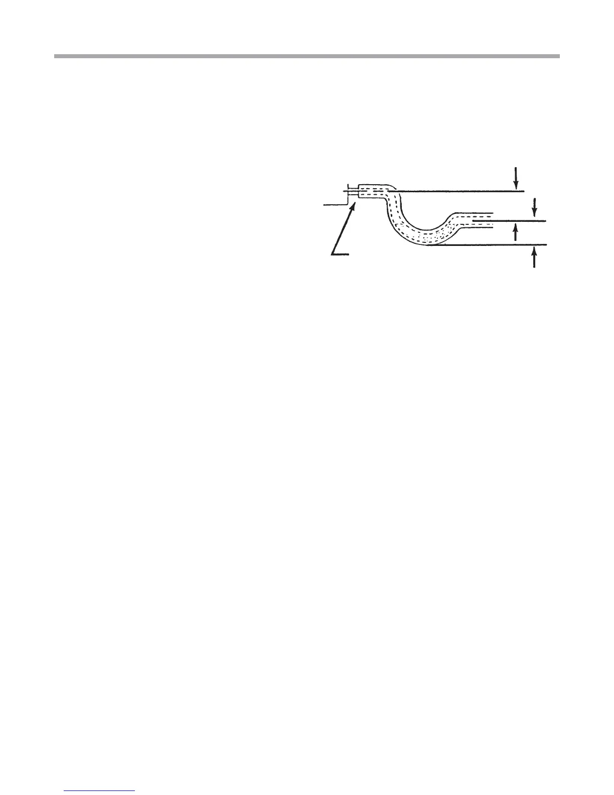
• Make provisions for disconnecting and cleaning of the
primary drain line should it become necessary. Install
a 3 in. trap in the primary drain line as close to the unit
as possible. Make sure that the top of the trap is below
connection to the drain pan to allow complete drainage of
pan (See Figure 4).
• Auxiliary drain line should be run to a place where it will
be noticeable if it becomes operational. Occupant should
be warned that a problem exists if water should begin
running from the auxiliary drain line.
• Plug the unused drain connection with the plugs provided
in the parts bag, using a thin layer of Tefl on paste, silicone
or Tefl on tape to form a water tight seal.
• Test condensate drain pan and drain line after installation
is complete. Pour water into drain pan, enough to fi ll
drain trap and line. Check to make sure drain pan is
draining completely, no leaks are found in drain line
fi ttings, and water is draining from the termination of the
primary drain line.
'2 127 23(5$7( 81,7 :,7+287
&21'(16$7( '5$,1 75$3
81,7 0867 %( 6/,*+7/< ,1&/,1('
72:$5' '5$,1 &211(&7,21
'2 127 29(57,*+7(1 '5$,1 ),77,1*
81,7
Installation
It is always recommended that an auxiliary drain pan be
installed under a horizontally installed air handler.
Connect the auxiliary drain line to a separate drain line (no
trap is needed in this line) and terminate according to local
codes.
NOTE: DO NOT use a torch or fl ame near the
plastic drain pan coupling.
NOTE: DO NOT tighten the drain pipe excessively.
Support the condensate piping and traps outside
the unit to prevent strain on the drain connection.
Figure 4: Condensate Drain Trap