AIR OUT
AIR OUT
AIR OUT
NRP
BLOWER
ROTATION
NRP
NRP
NRP
RETURN AIR
RETURN AIR
BLOWER TO AIR COIL
RELATIONSHIP FOR
REAR OR FRONT
DISCHARGE 072-120
RETURN AIR
UPA
BSP
BSP
2
2
2
3
4
4
5
CSP+CAP+MSP
1
1
1
CSP+CAP+MSP
CSP+CAP+MSP
4
4
5
7.6
F
L
K
M
SIDE
SERVICE ACCESS
(See Note 8)
SERVICE ACCESS
·&0
FRONT AND BACK
1.7
E
F
D
F
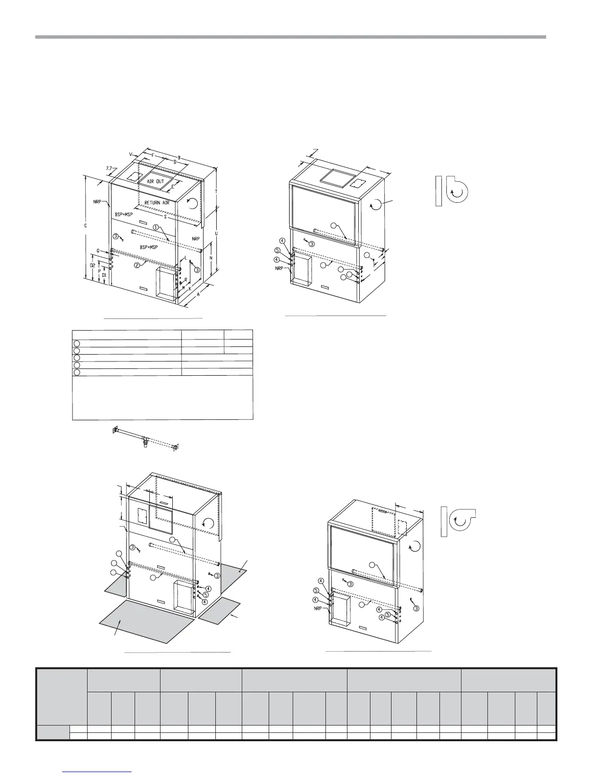
LEGEND
7&9
TCV120
Water Inlet (See Note 2)
Water Outlet (See Note 2)
Condensate Drain (See Note 3)
High Voltage Access (See Note 4)
Low Voltage Access (See Note 4)
1-1/4” FPT
1-1/4” FPT
1-1/2” FPT
1-1/2” FPT
1” FPT
µ>&0@
µ>&0@
BSP - Blower Service Panel
CAP - Control Access Panel
CSP - Compressor Access Panel
MSP - Motor Service Panel
NRP - Non Removable Panel
UPA - Upper Pulley Access
1
2
3
4
5
FRONT RETURN REAR DISCHARGE (FR/RD)
REAR RETURN FRONT DISCHARGE (RR/FD)
REAR RETURN TOP DISCHARGE (RR/TD)
FRONT RETURN TOP DISCHARGE (FR/TD)
NOTES:
All dimensions in table are inches (cm)
1. While access to all removable panels may not be required, installer should take care to
comply with all building codes and allow adequate clearance for future field service.
2. Water inlet and water outlet connections are factory shipped on the left side. Union
allows field conversion to right side.
3. Condensate drain is available on either side (left or right) of unit. Drain hose and drain
connection will be tied inside the unit. Installer will untie the drain hose, form trap, and
FRQQHFWWRWKHFRQGHQVDWHGUDLQKROHRILQVWDOOHU·VFKRLFH
4. Electrical access is available on either side (left or right) of unit and is also available in
the front on the left or right side of the unit.
5. Overall width - Add 3.12” (8cm) for 1“ (2.5cm) or 2” (5cm) Filter Frame; or 5.12” (13cm)
for 4” (10.2cm) and for front or rear supply add additional 1.06” (2.7cm) for supply
duct collar.
6. Overall cabinet height dimension does not include duct flange for top discharge
configuration.
8QLWVUHTXLUHIHHWFPFOHDUDQFH&$3&63063DQG%63VHUYLFHDFFHVV
6LGHVHUYLFHDFFHVVPXVWEHIHHWFPRQDQ\VLGHWKDWFRQQHFWLRQVDUHPDGH
)LOWHUUHPRYDOLVIURPULJKWRUOHIWVLGHRIILOWHUIUDPHDOORZIHHWFPDFFHVV
for servicing.
BSP
UPA
ALL CONFIGURATIONS REQUIRE SERVICE ACCESS AREA
DESCRIBED IN NOTES 7, 8, and 9
(See Notes 1 and 7)
(See Notes 1 and 7)
Note 2
ALL CONFIGURATIONS
BLOWER TO AIR COIL
RELATIONSHIP FOR
TOP DISCHARGE
072-120
BSP+MSP
CSP
(See Note 6)
Control
Box
Control
Box
Control
Box
Control
Box
in. 29.0 41.0 69.8 17.5 14.8 11.9 22.0 7.3 14.5 21.3 8.0 15.0 11.3 1.0 1.5 36.3 29.4 30.6 2.7
cm. 73.7 104.1 177.2 44.5 37.5 30.2 55.9 18.4 36.8 54.0 20.3 38.1 28.6 2.5 3.8 96.2 74.7 77.8 6.9