THE SMART SOLUTION FOR ENERGY EFFICIENCY
Tranquility
®
Compact Belt Drive (TCH/V) Series
Rev.: July 25, 2017
7
climatemaster.com
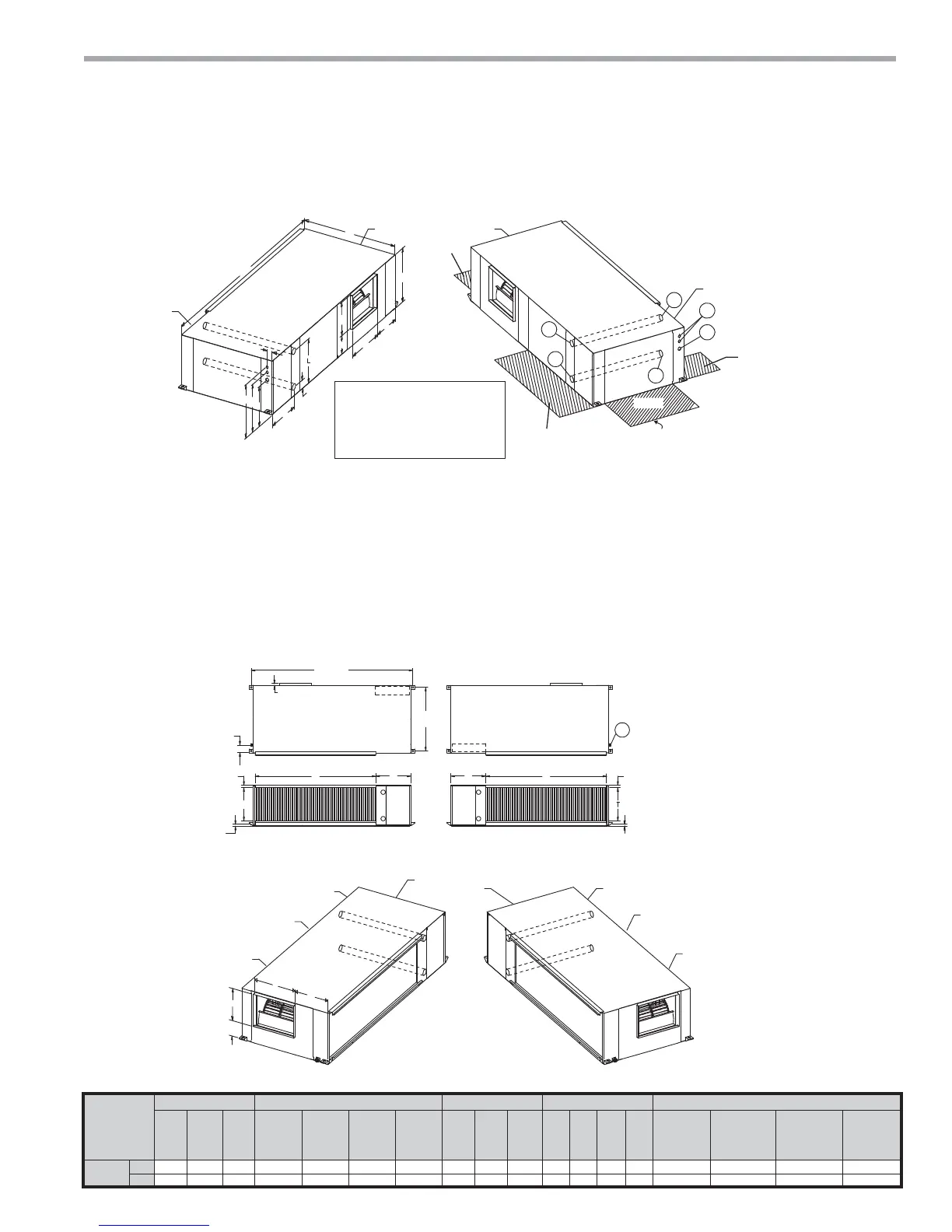
HANGER BRACKET DIMENSIONS
87”
[221cm]
1.0”
[2.54cm]
PLAN VIEW
TOP
4.3”
[10.8cm]
34.1”
[86.6cm]
FRONT
CONTROL BOX
U
T
S
V
1.3”
[3.3cm]
condensate
LEFT RETURN LEFT VIEW-
AIR COIL SIDE
LEFT RETURN END DISCHARGE
CBP
EAP
BSP
CAP
CAP
FRONT
E
D
F
G
CAP
CBP
CAP
EAP
BSP
FRONT
FRONT
CONTROL BOX
PLAN VIEW
TOP
V
S
U
RIGHT RETURN RIGHT VIEW-
AIR COIL SIDE
RIGHT RETURN END DISCHARGE
1.3”
[3.3cm]
condensate drain
3
TCH072-120 Dimensional Data
LEFT RETURN STRAIGHT DISCHARGE
CAP
CAP
FRONT
BSP
A
EAP
CBP
B
C
O
P
Q
R
K
M
F
G
E
D
BSP
RIGHT RETURN STRAIGHT DISCHARGE
1
EAP
2 CAP
CAP
2
FRONT
CBP
1
5
4
LEGEND
CAP=Compressor Access Panel
CBP=Control Box Panel
BSP=Blower Service Panel
EAP=Expansion Valve Access panel
1=Water Outlet 1-1/4” FPT (072-096) 1-1/2” FPT (120)
2=Water Inlet 1-1/4” FPT (072-096) 1-1/2” FPT (120)
3=Condensate 3/4” FPT
4=High Voltage 1-1/8” [2.9cm] KO
5=Low Voltage 7/8” [2.2cm] KO
SERVICE ACCESS
3’ (91 cm.)
Note 5, 6
Note 6
Note 6
Note 6
ALL CONFIGURATIONS REQUIRE SERVICE ACCESS AREA
DESCRIBED IN NOTES 5 AND 6.
NOTES:
-
All dimensions in table are inches (cm).
6HUYLFHDccess is required for all removable panels and installer should take care to comply with all building codes and
allowadequate clearance for future field service.
Water inlet and water outlet connections are available on either side (left or right) of the unit. Qty (2x) MPT Plugs are
shipped loose in a plastic bag tied to the water leg in front of the unit. Installer must plug water inlet/outlet side not being
connected to.
&RQGHQVDWHGUDLQLV)37DQGLVORFDWHGRQFDELQHWHQGRSSRVLWHWKHFRPSUHVVRU
Electrical access is available on either side (left or right) of the front.
Electric box is on right side. It can be field converted to left side. Conversion should only be attempted by qualified
service technician. If electric box relocated to opposite side, and water connected to opposite side, then this access is
not required.
Units require 3’ (9.1 cm) clearance for water connections, CAP, C%P, EAP and BSP service access.
Overall cabinet width dimensions does not include filter rail and duct flange.
8QLWVDUHVKLSSHGZLWKDLUILOWHUUDLOVWKDWDUHQRWVXLWDEOHIRUVXSSRUWLQJUHWXUQDLUGXFWZRUN$QDLUILOWHUIUDPHZLWKGXFW
PRXQWLQJFROODULVDYDLODEOHDVDQDFFHVVRU\
TCH072-120 Dimensional Data
Model
Overall Cabinet Discharge Connections Duct Flange Water Connections Electrical Knockouts Return Air Connections Using Return Air Opening
A
Depth
B
Width
C
Height
DE
Supply
Depth
F
Supply
Width
G
Supply
Height
KL
1
Water
Outlet
M
2
Water
Inlet
OPQR S
Return
Depth
T
Return
Height
UV
072-120
in.
36.3 84.9 21.6 14.0 17.0 13.5 7.8 15.0 8.3 4.0 2.0 18.8 16.8 13.8 65.0 18.0 1.0 18.9
cm.
92.2 215.6 54.9 35.6 43.2 34.3 19.8 38.1 21.1 10.2 5.1 47.8 42.7 35.1 165.1 45.7 2.5 48.0