09
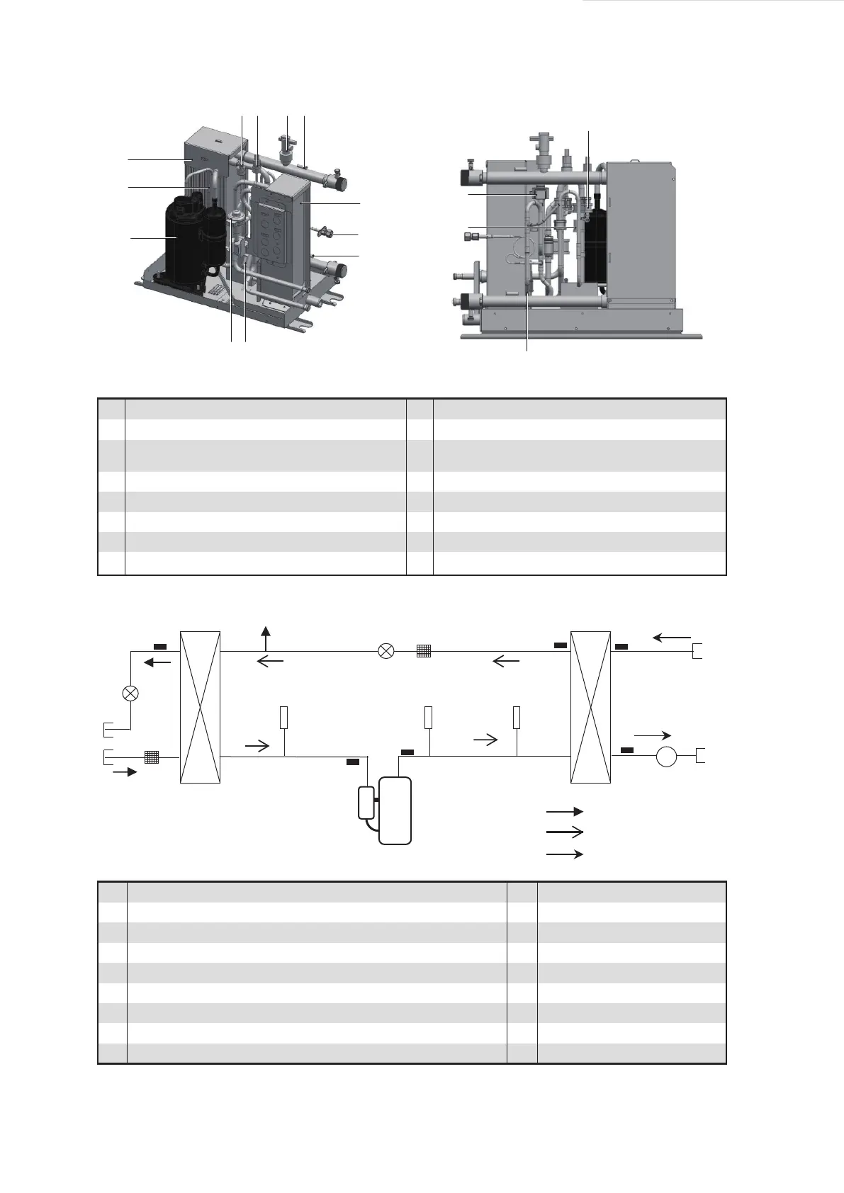
Compressor
Discharge temperature sensor
Plate heat exchanger used as condenser
Low pressure sensor
High pressure sensor
Water flow switch
Water outlet temperature sensor
Plate heat exchanger used as evaporator
Service pot
Water inlet temperature sensor
Electronic expansion valve on the R410A loop
High pressure switch
Electronic expansion valve on the R134a loop
Suction temperature sensor
Liquid pipe temperature on the R134a loop
Main parts of the unit
1
2
3
4
5
6
7
8
9
10
11
12
13
14
15
16
Liquid pipe temperature sensor at the outlet on the
R410A refrigerant side
Compressor
Plate heat exchanger used as condenser
Electronic expansion valve 1 on the R134a loop
Plate heat exchanger used as evaporator
Electronic expansion valve 2 on the R410A loop
Discharge pipe temperature sensor
Suction pipe temperature sensor
Liquid pipe temperature sensor on the R134a loop
Liquid pipe temperature sensor on the R410a loop
Water inlet temperature sensor
Water outlet temperature sensor
Water flow switch
High pressure sensor
Low pressure sensor
High pressure switch
Filter
Service pot
1
2
3
4
5
6
7
8
9
10
11
12
13
14
15
16
17
1
15
13
6
2
10
3
4
14
7
16
5
11
9
8
17
F
12
16
R410a flow route
R134a flow route
Wafer flow
Connecting pipes on the refrigerant side and water system side (For details, see the installation diagram on page 6.)
15
16
14
8
9
10
13
7654
3
2
1
12 11
 Loading...