08
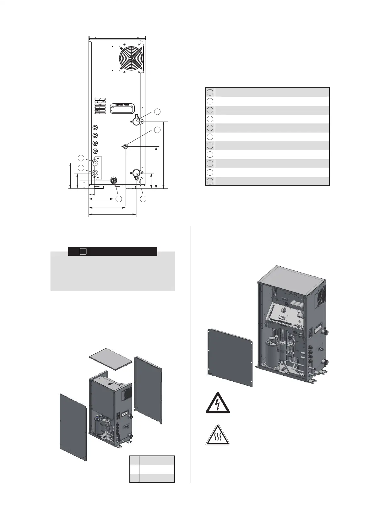
Liquid pipe (connected to the ODU)
Gas pipe (connected to the ODU)
Water discharge pipe (drainage pan)
Y-shaped filter
Access hole (for charging/discharging refrigerant)
Water discharge pipe (safety valve)
Safety valve
Discharge valve
Drain valve
Water inlet
Water outlet
D
D
E
E
F
F
G
H
H
I
J
K
L
M
M
N
N
32
130
80
42
80
135
218
348
192
248
5 UNIT INSTALLATION
INFORMATION
i
The unit should be installed by professional
installation operators. Material selection and
installation should conform to the corresponding
legal provisions.
Checking the main parts of the unit
To check the interior of the unit, open the top panel, front
panel, and rear panel first. After you open these three
panels, you can see the main parts of the unit. If you just
install or maintain the internal parts of the electric control
box, you need to open the front panel without needing to
open the top or rear panel
2
1
3
1
2
3
Top panel
Front panel
Rear panel
To open the electric control box and operate the interior
of the electric control box, open the electric control box
cover plate. To open the electric control box, you can
open the front panel without needing to open the top or
rear panel.
Danger: Electric shock
See "1.2 General Safety Precautions"
on page 2.
Danger: Do not touch pipes or internal
parts. See "1.2 General Safety
Precautions" on page 2.
 Loading...