7
General Details
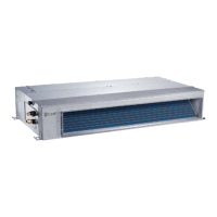
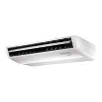
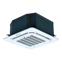
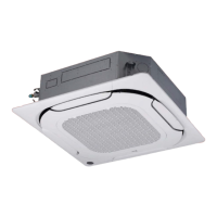
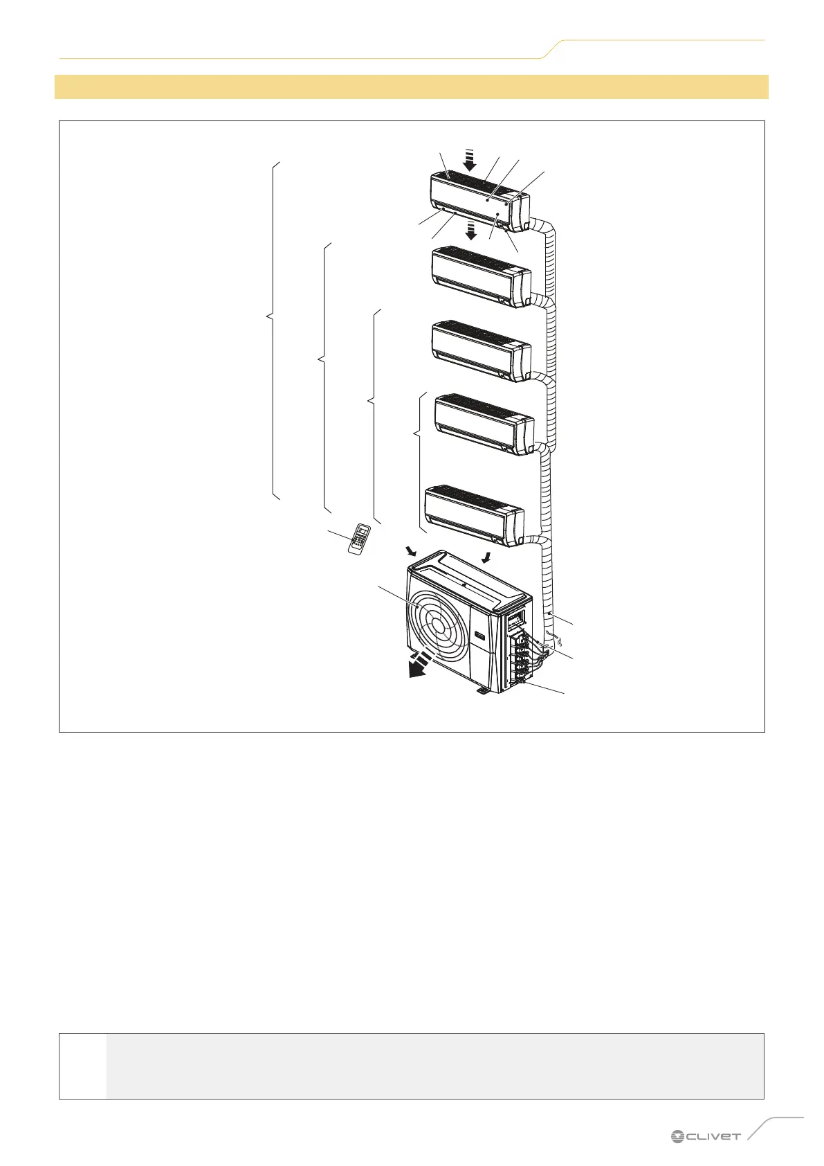
1.3 Description of MULTISplit system components
B
B
5
8
6
7
1
2
3
4
9
1 x 4
1 x 3
1 x 2
13
11
Fig. 2
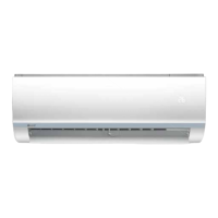
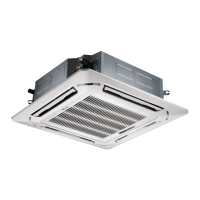
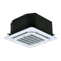
Indoor unit
1 Panel frame
2 Rear air intake grille
3 External panel
4 Purifier filter and air filter (on the back)
5 Horizontal ventilation flap
6 LCD display window
7 Vertical ventilation flap
8 Manual control button
9 Remote control support
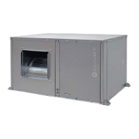
Outdoor unit
10 Drain pipe, refrigerant connection pipe
11 Connection cable
12 Stop valve
13 Fan cover
A Air inlet
B Air outlet
l
WARNING
The images in this manual are provided for illustrative purposes only. The appearance of your device may
dier slightly from the illustrations shown here. Refer to the actual characteristics of the unit.