23
DrivenClutchGASOLINEVEHICLE-CLUTCHES
5.1.2.Holdthexedsheave(3)androtatethemoveablesheave(1)one-thirdturncounterclockwise,
thenpressthecam(2)ontothexedsheave(Figure23-17,Page23-16).Thematchmarks
madebeforedisassemblyshouldnowalign.
5.1.3.Installtheretainingring(4)(Figure23-15,Page23-15).SeefollowingNOTE.
NOTE:Theretainingring(4)canbereusediftheO.D.doesnotexceed1.607in.(40.82mm);otherwise,itmust
bereplacedwithanewring.
5.1.4.Whileholdingontothecam,taptheendofthexedsheavelightlywithaplasticmalletuntilthecam
seatsagainsttheretainingring(4).SeefollowingCAUTION.
CAUTION
•Donotuseametalhammertotapthexedsheave.Ametalhammerwilldamagetheshaft.
611
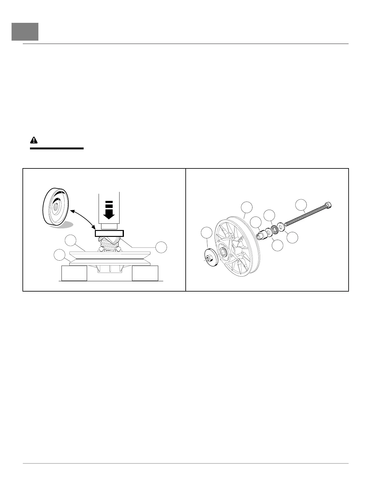
Figure23-17CamPressTool
612
Figure23-18CamInstallationTool
5.2.FieldAssemblyProcess:
NOTE:Thisprocessisforeldassemblyrequirementswherehydraulicandpneumaticpressequipmentisnot
available.Usethecaminstallationtoolforthisprocess.
5.2.1.Withtheclutchlooselyassembled,settheedgeoftheclutchbody(5)onaclean,atsurface
(Figure23-18,Page23-16).
5.2.2.Assemblethethreadedbolt(1)throughthewasher(2),thethrustbearingassembly(3),thesecond
washer(2),andthehubguide(4).
NOTE:Itisveryimportantthatthebolt,washers,andthrustbearingassemblybeassembledintheorderdescribed
andshown.
5.2.3.Slidethebolt(1)throughtheclutchbody(5)untilthethreadedbolt,washers,bearing,andhub
guideareagainstthexedsheave(Figure23-18,Page23-16).
5.2.4.Holdtheclutchassemblyandcaminstallationtooltogetherandplacethexedsheavedownon
spacedblocks(Figure23-17,Page23-16).
5.2.5.Placethecampresshub(6)ontothecaminstallationboltandthreaditdownontothecamhub,
centeringthepresshubontothecamhub.
Page23-162019PrecedentVillager2MaintenanceandServiceManual

 Loading...