MAN. 126 rev.4 Use and maintenance manual S19
22 of 77
The emergency station control panel is placed on the right of the turret and
is formed by:
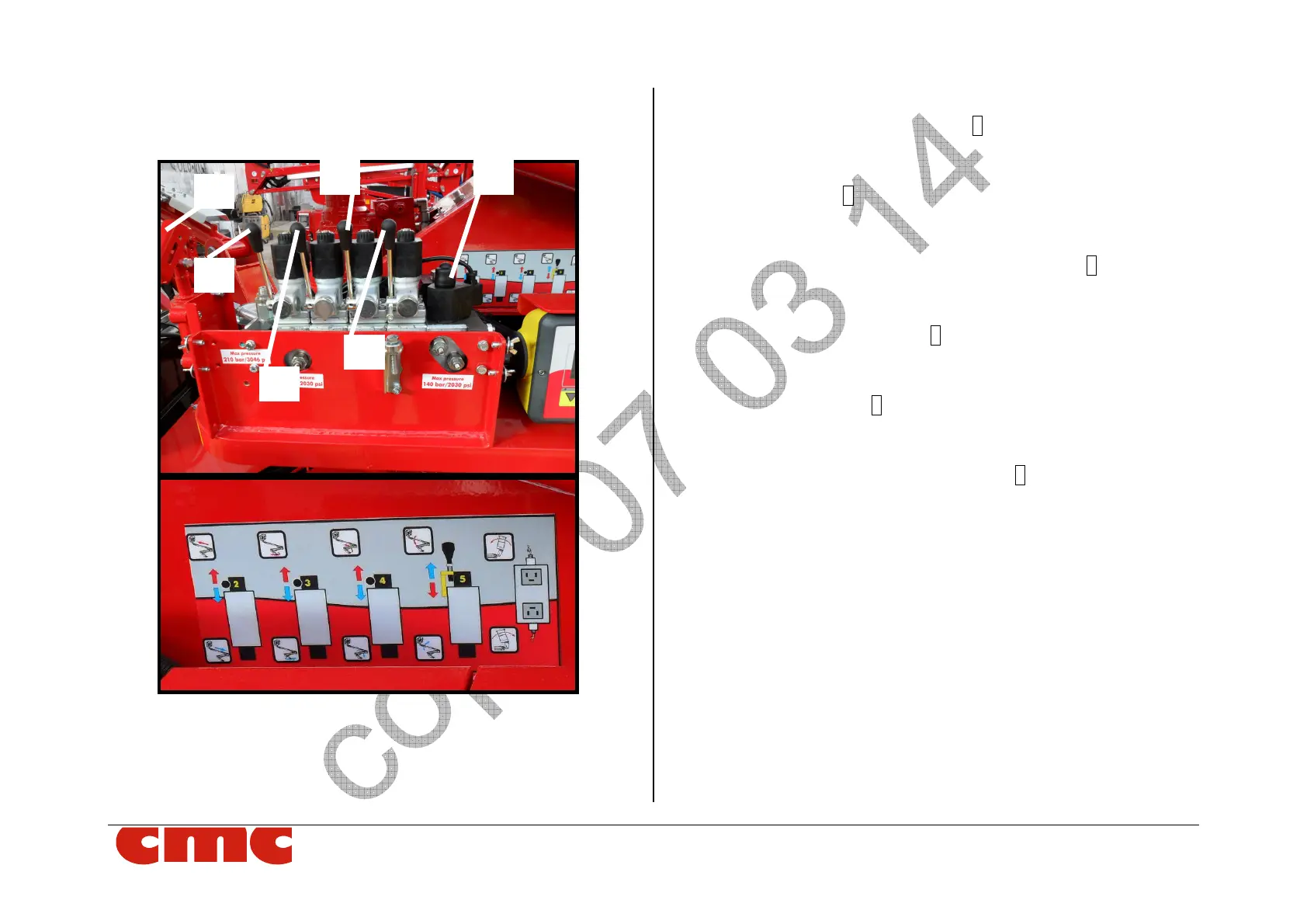
Picture 18: platform control (emergency) station
The emergency station control panel is placed on the right side of the turret
as viewed from the basket. Components:
-Boom extension - retraction 2 (Picture 18): Activates the
extension (lever upwards) and retraction (lever downwards);
Movement stops when lever is released.
-Turret rotation 3 (Picture 18): activates MEWP CW rotation (lever
upwards) and CCW rotation (lever downwards); movement stops
when lever is released.
-Raise - Lower of (lower boom) pantograph 4 (Picture 18):
Operates and raises (lever upwards) and the lowering (lever
downwards); movement stops when lever is released.
-Raise- Lower upper boom 5 (Picture 18): operates raising lifting
(lever downwards) and the lowering (lever upwards); movement
stops when the lever is released.
-Basket levelling 6 (Picture 18): activates basket levelling
forward(push button upwards) and basket levelling backwards (push
button downwards);
-Manual hydraulic pump and lever 7 (Picture 18): used to
manually operate the hydraulic system in case of either diesel
engine or electrical motor failure (lack of fuel or lack of electric
power, etc. Requires additional operator help to operate.