CNC-STEP GmbH & Co. KG ▪ Siemensstrasse 13-15 ▪ 47608 Geldern ▪ Germany
Support: +49 (0)2831/91021-50
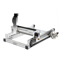
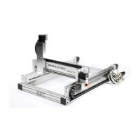
4.5 Connections
The connectors of the step motor cables or control line ST are
labelled as follows:
• Connector X1 stepping motor of the X-axis.
• Connector X2 stepping motor of the X-axis.
• Plug Y stepping motor of the Y-axis.
• Plug-Z stepper motor Z-axis.
• Connector ST Emergency, Ref-switch and socket Pin15.
Fig. 13: Connection ST and. Motor
connection
The connection of the stepper motors or the reference
switch and emergency stop signal are carried out via
depicted lines marked on each Sub-D connector (Fig. 13).
For pin assignment see Figure 14 and Figure 15.
Ground Connection to Zero-3 Controller
 Loading...