Chapter 3: Connectors & controls
14 Connectors
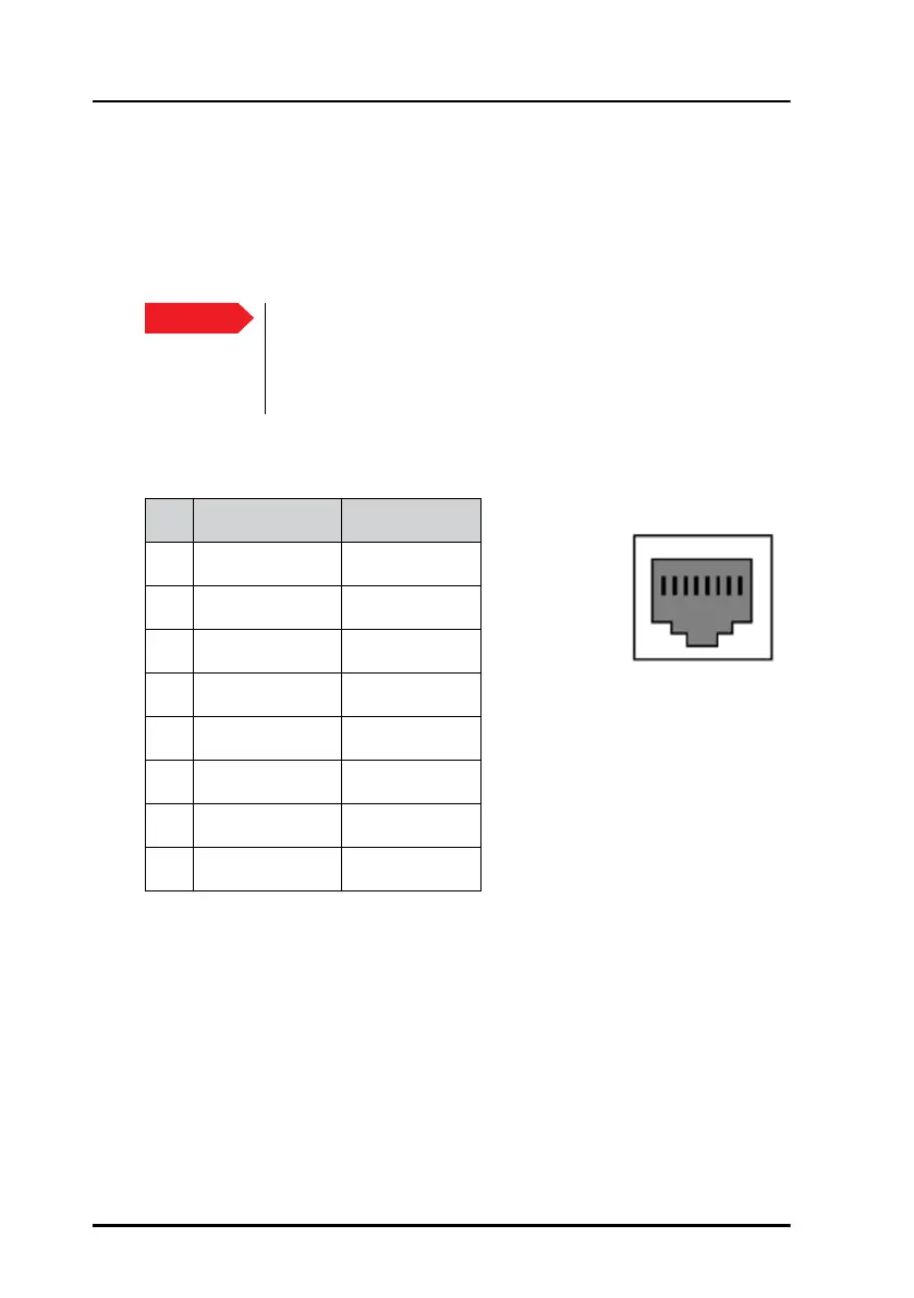
LAN connector
There are two LAN (10/100 Mbit/s Ethernet) connectors on the rear panel
of the Control Panel, used for communication with connected equipment
that is designed to be operated by the Control Panel.
The figure and table below show the connector outline and pin
assignments.
Important
For GMDSS installations: Only connect units that are part
of the system. For safety and compliance reasons, the
Ethernet interface is restricted to communication in an
isolated system.
Pin Pin function Wire colour
1 Tx+ White/Orange
2 Tx- Orange
3 Rx+ White/Green
4 Not connected Blue
5 Not connected White/Blue
6 Rx- Green
7 Not connected White/Brown
8 Not connected Brown
RJ-45 female
1 2 3 4 5 6 7 8