TN152 Linked Repeater Networks
MT-3/4 Radio Systems
TECHNICAL NOTES
Page 2 of 4
LMRSALES@CODANCOMMS.COM
CODANCOMMS.COMTECHNICAL NOTE:
TN152, REV 1-0-0, © Jan 2019
CANADA/US +1 250 382 8268 | TOLL FREE +1 800 664 4066
Technical Description
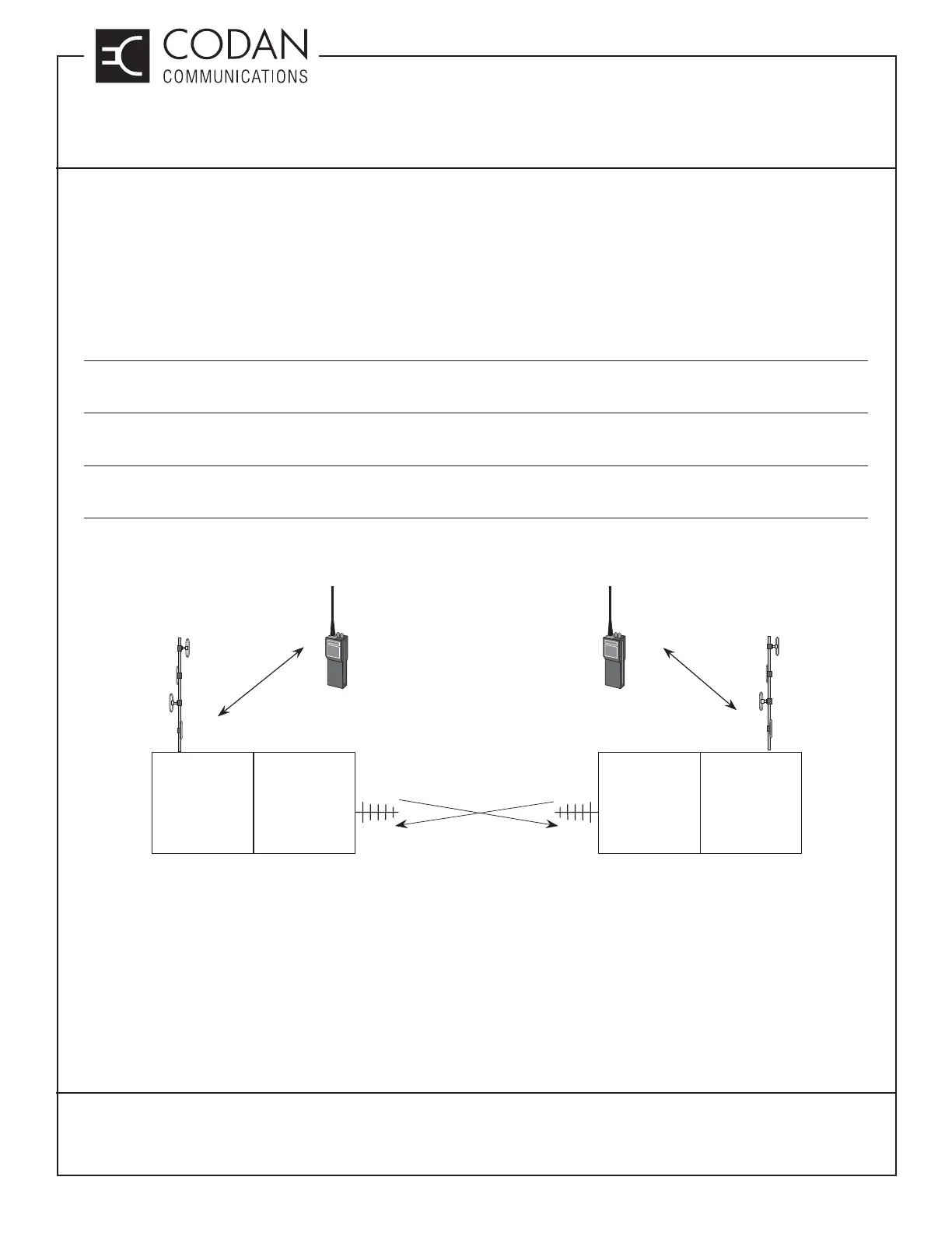
Linked repeaters are made up of two transceivers, the repeater (sometimes referred to as the “Drop”), and the
Link. The Drop repeaters are on separate frequencies, while the link frequencies are matched (and reversed).
Figure 2 shows two repeaters linked together with frequency pairs. The Link is referred to as a “Switched Link”,
meaning that the receiver and transmitter are never active at the same time.
A Switched Link is typically half-duplex, allowing use of a duplexer or antenna relay for the antenna connection.
• An antenna relay allows for a more frequency agile link, transceiver frequencies can be changed without the
need for any duplexer retuning.
• A duplexer allows the Switched Link to be changed to a Repeating Link if the system needs to be expanded for
more linked repeaters.
• Simplex (same) frequencies can also be used on a two site Switched Link repeater with an antenna relay, but
every linked repeater must Link directly to each other (no “Chains” of links).
The use of diff erent repeaters all transmitting at the same time on diff erent frequencies is called multicasting.
Figure 2: Network of Two Repeaters
Site 1 Site 2
Drop
Switched link
Tx-F1
Rx-F2
Tx-F3
Rx-F4
Drop
Switched link
Tx-F4
Rx-F3
Tx-F5
Rx-F6
To / From
Subscribers
To / From
Subscribers