MT-3/4 Radio Systems
TECHNICAL NOTES
Page 1 of 2
LMRSALES@CODANCOMMS.COM
CODANCOMMS.COMTECHNICAL NOTE:
TN870, REV 2-1-0, © Mar 2013
CANADA/US +1 250 382 8268 | TOLL FREE +1 800 664 4066
TN870 CI-RSWITCH Redundant Switch
The CI-RSWITCH is a low current, high reliability redundant switch capable of operating at extreme temperatures in
remote locations. The CI-RSWITCH Redundant Switch Module provides a simple interface between two redundant
radio systems composed of Codan receivers, transmitters, amplifi ers and controllers.
The Redundant Switch Module allows the Main or Backup radio system to be selected for operation and can be
connected to various alarm modules such as the Power Monitors to control the switching function. The Redundant
Switch transfers voltage inputs between the Main and Backup systems, and connections to two high quality RF
relays are provided to permit the two redundant radio systems to share single antenna systems. The Redundant
Switch is 19” rack mounted (1 RU height) and provides DC power to the selected Main and Backup repeater
systems.
The Redundant Switch provides the following features:
• average current draw of 19 mA .
• RF relay switching current of 200 mA for 15 ms maximum.
• input current distribution of up to 40 Amps.
• six active low momentary Alarm inputs.
• two active low momentary Reset inputs.
• one active low Backup Test enable input for testing / tuning purposes.
• two open collector Alarm outputs. Alarm 1 will short to ground to indicate Main operation and Alarm 2 will short to
ground on Backup operation.
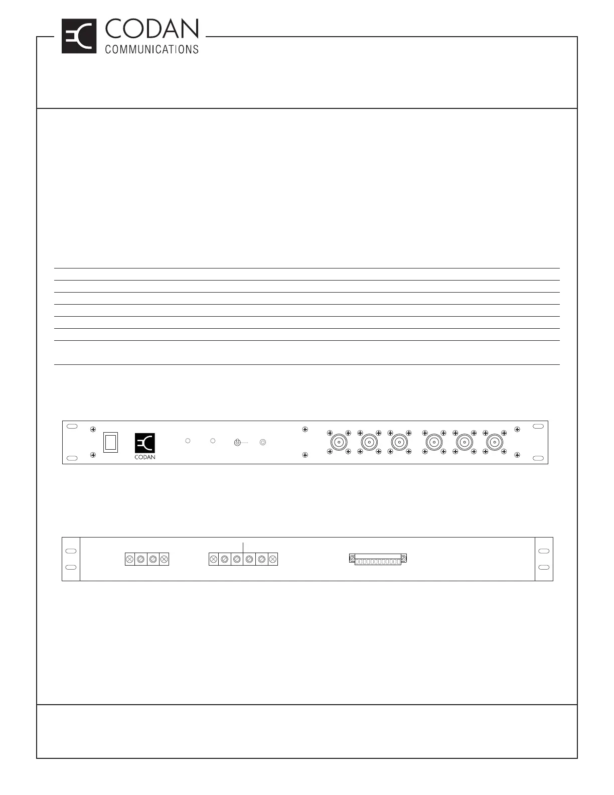
RF Relays, Backup Test switch, Main / Backup Indicator LEDs and the System Reset switch are all located on the
front panel of the Redundant Switch as shown in Figure 1.
Figure 1: Redundant Switch Front Panel
Power connections, alarm inputs, reset inputs, backup test input and alarm outputs are all located on the back panel
of the Redundant Switch as shown in Figure 2.
Figure 2: Redundant Switch Rear Panel
REDUNDANT SWITCH
Primary
Power
Status
Indicators
Main
Backup
Backup
Tes t
ON
OFF
System
Reset
Main BOutput BBackup B
Main AOutput A
Backup A
Power Input
(+13.8 Nominal)
Input Range
(12.0V to 17.0V DC)
+
-
+
-
+
-
Main Backup
Power O/P Power O/P
J1 Monitor & Control
112