TN500 SR-39-1 Subrack
MT-3/4 Radio Systems
TECHNICAL NOTES
Page 1 of 4
LMRSALES@CODANCOMMS.COM
CODANCOMMS.COMTECHNICAL NOTE:
TN500, REV 5-0-0, © Aug 2016
CANADA/US +1 250 382 8268 | TOLL FREE +1 800 664 4066
The SR-39-1 subrack is designed to hold and interconnect the MT-3 and MT-4 series of receiver, transmitter
and control modules on one universal motherboard. This Type 84 motherboard makes extensive use of cage
jacks to interconnect the A and B systems supporting a number of fi eld confi gurations. Additional auxiliary control
connectors provide easy access to virtually all control and audio lines, simplifying many standard base / repeater
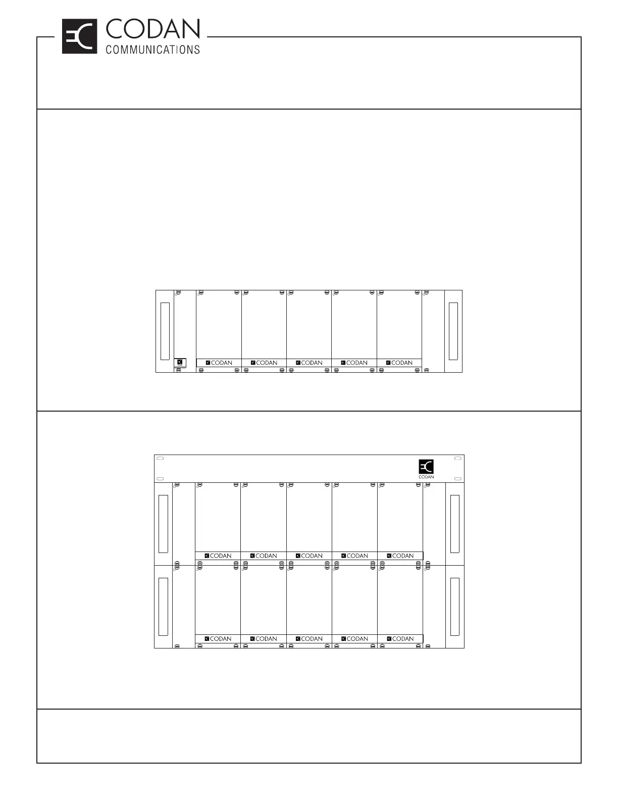
confi gurations. Modules may be inserted in the subrack in many various confi gurations as shown in Figure 1. The
Control 1 connector is used for the base or repeater control card or paging modulator. The Optional Control 2 card
is for custom systems requiring specialized paging / data / audio interconnections and is not normally used. If the
radio system is ordered with antenna relays, the system regulator with the relays is housed in a larger module that
encompasses the area for the Control 2 module. The subrack has room for two transmitter and receiver pairs. The
left side connectors are reserved for transmitter and receiver A (C in second subrack) respectively, while the right
side connectors are reserved for transmitter and receiver B (D in second subrack). Although any transmitter and
receiver can be placed in either of the respective slots, convention usually follows that the lower frequency radios
will go in slots A and the higher in slots B to D.
Figure 1: Standard Subrack
A quadruple system is shown in Figure 2 with A and B pairs in the fi rst rack, and C and D pairs in the second rack.
This system requires a multiple link controller and two system regulators.
Figure 2: Dual Subracks for Multiple Link Confi guration
SYSTEM
REGULATOR
RECEIVER
B
TRANSMITTER
B
RECEIVER
A
TRANSMITTER
A
CONTROL
1
OPTIONAL
CONTROL
2
SYSTEM
REGULATOR
RECEIVER
D
TRANSMITTER
D
RECEIVER
C
TRANSMITTER
C
BLANK
PANE L
BLANK
PANE L
SYSTEM
REGULATOR
RECEIVER
B
TRANSMITTER
B
RECEIVER
A
TRANSMITTER
A
BLANK
PANE L
BLANK
PANE L
MULTIPLE LINK CONTROLLER