MT-3/4 Radio Systems
TECHNICAL NOTES
Page 1 of 2
TN441 AMP-4 VHF and UHF 30 Watt Power Amplifi ers
LMRSALES@CODANCOMMS.COM
CODANCOMMS.COMTECHNICAL NOTE:
TN441, REV 2-0-0, © Jul 2013
CANADA/US +1 250 382 8268 | TOLL FREE +1 800 664 4066
The AMP-4 30 Watt power amplifi er operates in one of three frequency bands: 136
to 174 MHz, 380 to 430 MHz or 450 to 520 MHz. The power amplifi er is rated for
continuous duty at an adjustable RF output power of 20 to 30 Watts. The output
power is adjusted either using the front panel potentiometer (local mode) or by a
voltage via the rear panel connector (remote mode). The local and remote mode
output power control is determined by a hardware jumper on the inside of the power
amplifi er. The AMP-4 was designed to mate with any of the MT-3 / MT-4 transmitter
exciter modules.. The input to the power amplifi er cannot exceed 8.0 Watts.
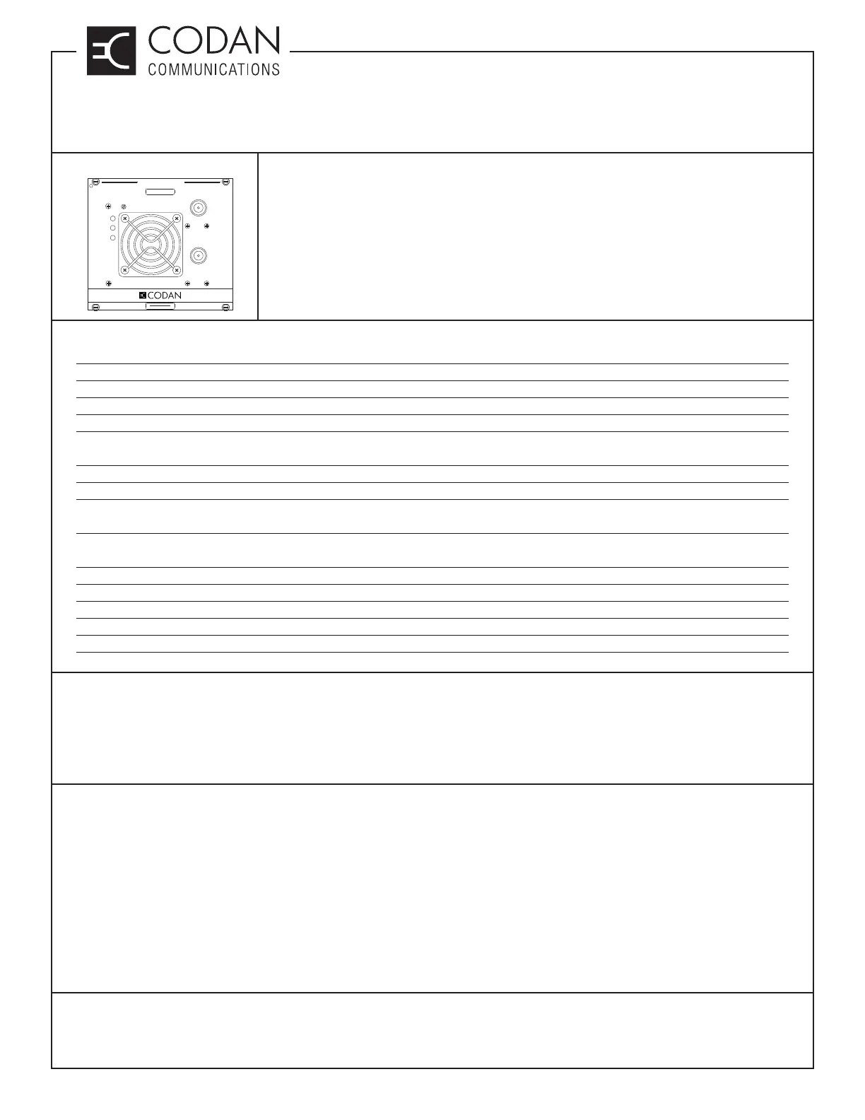
POWER AMPLIFIER
TX
G/F
VSWR
RF OUTPUT
RF INPUT
PWR CTRL
FREQUENCY (MHz)
MADE IN CANADA
MODEL # CODE
Specifi cations
Frequency Band 136 - 174 MHz / 380 - 430 MHz / 450 - 520 MHz
RF Output Power 20 to 30 Watts adjustable
RF Input Power Range (from exciter) 6.4 to 8.0 Watts (VHF) / 6.0 to 8.0 Watts (UHF)
Duty Cycle 100% (-30°C to +60°C)
Undesired Emissions: Conducted Spurious ≤ -70 dBc
(Includes Harmonics)
Undesired Emissions: Radiated Spurious ≤ -13 dBm (≤ 57.8 dBc)
Intermodulation Attenuation ≥ 40 dB
Thermal Thermal interlock disables @ +80°C (± 5°C) / +176°F
Resets at +70°C (± 7°C) / +158°F
Fan Fan activates @ +60°C (± 5°C) / +140°F
Resets @ +40°C / +104°F
VSWR Protection ≤ 20:1 VSWR (All Phase Angles)
Operating Temperature -30°C to +60°C
Output Impedance 50
Standby Current Drain ≤ 5 mA
Transmit Current Drain ≤ 7.00 A
Models Available
AMP-4-150-30-00 FM, 20 - 30 Watts continuous duty, 136 - 174 MHz
AMP-4-410-30-00 FM, 20 - 30 Watts continuous duty, 380 - 430 MHz
AMP-4-470-30-00 FM, 20 - 30 Watts continuous duty, 450 - 520 MHz
Guide Rails in Subrack for Power Amplifi er:
The AMP-4 is installed in the subrack (taking up a transmitter and receiver slot) and is mated with a transmitter
exciter. Additional guide rails are required to be mounted in the subrack to support the AMP-4 properly. The
amplifi er can be mounted in slot “A” or slot “B” in the subrack. A guide strip at the top of the subrack will help to
place the guide rails in the proper position by following the numbers on the guide strip. Only the top portion of the
subrack is labeled. Guide rails must be added or removed in the same position on the bottom as on the top.
Remove any guide rails that were used to hold the AMP-2 amplifi er. These guide rails will be located at number
20/21 for slot “A” and number 48/49 for slot “B”. Install guide rails at number 11/12 and 34/35 for slot “A” and number
39/40 and 62/63 for slot “B”.