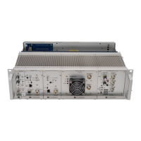
TN160 Base Station or Link Confi guration Settings
MT-3/4 Radio Systems
TECHNICAL NOTES
Page 1 of 2
LMRSALES@CODANCOMMS.COM
CODANCOMMS.COMTECHNICAL NOTE:
TN160, REV 5-0-0, © Nov 2018
CANADA/US +1 250 382 8268 | TOLL FREE +1 800 664 4066
When confi guring a Codan radio system for base station operation or for a linked confi guration, certain settings,
such as jumpers, may need to be installed to allow the base station or link to operate properly.
The receiver and transmitter modules are used with specifi c control cards to facilitate the external connections of a
base station, or to allow the complex connectivity of a linked system. The MT-3 modules are connected to an AC-3E
Audio Control Card and the MT-4 modules are connected to a CI-BC-4E Base Controller for base station operation,
or a CI-RC-4L Repeater Controller or CI-RC-4M-G2 Multiple Link Controller for a linked system. The A-PNL-
AUX96-3 auxiliary connector is recommended for facilitating all external connections in a base confi guration.
Antenna Relay Activation
The System Regulator module may have up to two optional antenna relays installed that can be used for a base
station or simplex / half-duplex link confi guration. The antenna relays are labeled as Relay A and Relay B (if only
one relay is installed, it is Relay A). The motherboard on the subrack contains a set of jumpers that are used to
activate the optional antenna relays in the System Regulator module. The relays are typically set with the PTT IN
and PTT OUT signal lines activating the relays.
Jumpers function as follows:
JU36 Tx A PTT OUT activates Relay A JU37 Tx A PTT IN activates Relay A
JU39 Tx A PTT OUT activates Relay B JU40 Tx A PTT IN activates Relay B
JU42 Tx B PTT OUT activates Relay A JU43 Tx B PTT IN activates Relay A
JU45 Tx B PTT OUT activates Relay B JU46 Tx B PTT IN activates Relay B
On older motherboards (Serial # 123125 and earlier) the jumpers were as follows:
JU16 Tx A PTT OUT activates Relay A JU12 Tx A PTT IN activates Relay A
JU14 Tx A PTT OUT activates Relay B JU10 Tx A PTT IN activates Relay B
JU15 Tx B PTT OUT activates Relay A JU11 Tx B PTT IN activates Relay A
JU13 Tx B PTT OUT activates Relay B JU9 Tx B PTT IN activates Relay B
Simplex Operation
The motherboard on the subrack contains a set of jumpers that are enabled when the radio system is operated in
simplex mode (simplex base station or simplex links). The jumper connects the Transmitter PTT OUT signal line to
the RX MUTE. This jumper will cause the receiver to mute when the transmitter is keyed.
JU38 Tx A PTT OUT mutes Rx A JU41 Tx A PTT OUT mutes Rx B
JU44 Tx B PTT OUT mutes Rx A JU47 Tx B PTT OUT mutes Rx B
The new System Regulators also have the same simplex mode jumpers for backwards compatibility with older
motherboards that did not have these jumpers. The jumpers were located on the old System Monitor as follows:
JU12 Tx A PTT OUT mutes Rx A JU13 Tx B PTT OUT mutes Rx B

 Loading...