TN367 UT-4E UHF MT-4E Transmitter
MT-4 Radio Systems
TECHNICAL NOTES
Page 1 of 2
LMRSALES@CODANCOMMS.COM
CODANCOMMS.COMTECHNICAL NOTE:
TN367, REV 5-0-0, © May 2014
CANADA/US +1 250 382 8268 | TOLL FREE +1 800 664 4066
The UT-4E UHF transmitter is an FM radio module capable of analog operation in 12.5 KHz
(narrowband) or 25 KHz (wideband) channels. A fi rmware upgrade may be purchased to
allow P25 digital operation. The UT-4E UHF transmitter operates in one of three frequency
bands: 380 to 406 MHz, 406 to 470 MHz or 470 to 520 MHz. A modular design allows each
of the transmitter’s internal modules to be individually assembled and tested. This facilitates
construction, tuning and maintenance as well as troubleshooting procedures. The transmitter
can be programmed with up to 2 banks of 16 channels each.
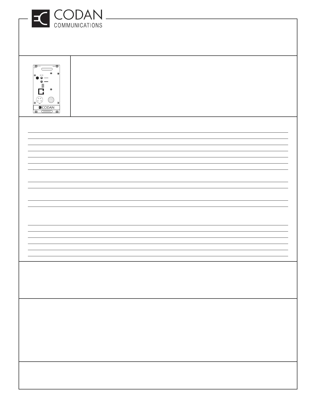
TRANSMITTER
CNTL
BUS
MIC RF OUT
AD
ANALOG
DIGITAL
NORM
OFF
KEY TX
MICMODE
REF
IN
USB
FREQUENCY (MHz)
MADE IN CANADA
MODEL # CODE
Specifi cations
Frequency Bands 380 - 406 / 406 - 470 MHz / 470 - 520 MHz
Channel Spacing 12.5 and 25 KHz
Frequency Switching Range Full Band; ± 0.5 MHz for VSWR alarm
RF Output Power 0.5 to 8.0 Watts adjustable or 0.5 to 6.0 Watts adjustable
Duty Cycle 100% (-30°C to +60°C)
Undesired Emissions (Conducted Spurious) ≤ -70 dBc (-31 dBm @ 6 / 8 W) 380 & 450; (-32 dBm @ 6W) 500
Undesired Emissions ≤ -60 dBc; Narrowband Analog / ≤ -70 dBc; Wideband Analog
(Adjacent Channel Power Ratio) ≤ -67 dBc; Digital
Intermodulation Attenuation ≥ 40 dB (380) / ≥ 45 dB (450 & 500)
FM Hum & Noise Ratio ≥ 40 dB NB ; ≥ 46 dB WB (380) / ≥ 38 dB NB ; ≥ 44 dB WB (450)
≥ 34 dB; NB ; ≥ 40 dB; WB (500)
Carrier Frequency Stability ± 0.5 ppm (-30°C to +60°C)
Emission Designators Analog: 11K0F3E (Narrowband); 16K0F3E (Wideband)
Paging: 9K20F1D
P25 Digital: 8K10F1E (Digital Voice); 8K10F1D (Digital Data)
Audio Distortion (60% of maximum deviation) ≤ 3.0% (-30°C to +60°C)
VSWR Protection ≤ 20:1 VSWR (All Phase Angles)
Operating Temperature -30°C to +60°C
Standby Current ≤ 50 mA / ≤ 80 mA with encryption module
Transmit Current (8.0 W) ≤ 2.80 A
Models Available
UT-4E380-00-800 12.5 / 25 KHz Bandwidth, 0.5 - 6.0 W, 380 - 406 MHz
UT-4E450-00-800 12.5 / 25 KHz Bandwidth, 0.5 - 8.0 W, 406 - 470 MHz
UT-4E500-00-800 12.5 / 25 KHz Bandwidth, 0.5 - 6.0 W, 470 - 520 MHz *Not available in Canada
Transmitter Operating Frequency
The transmitter is initially aligned at the factory for the frequency shown on the label on the front panel. For a small
frequency change, no re-alignment of the transmitter may be required. If the frequency change is greater than
±0.5 MHz from the frequency at which the last complete transmitter alignment was performed, the VSWR alarm
/ overload (if used) will need to be realigned. To align and / or adjust the transmitter, the outer cover needs to be
removed; the transmitter needs to be plugged into the subrack via a cable and / or extender card; and power must
be applied to the system. A 50 dummy load should be connected to the RF output when transmitting.