TN835 High Current AC to DC Power Supplies
MT-3/4 Radio Systems
TECHNICAL NOTES
Page 1 of 2
LMRSALES@CODANCOMMS.COM
CODANCOMMS.COMTECHNICAL NOTE:
TN835, REV 1-1-0, © Mar 2013
CANADA/US +1 250 382 8268 | TOLL FREE +1 800 664 4066
The PSA-12-40-RB-00 and PSA-12-60-RB-00 AC switching power supplies provide a regulated +13.8 Vdc to the
output terminals. The power supplies are 19” rack mountable and include battery revert capability. An input fuse,
electronic current limiting and voltage limiting protection, transient voltage suppressor and thermistor are built into
the unit as standard protection to safeguard the unit from abnormal conditions. The power supply uses active
current sharing technology to distribute the load current among two or three 20 Amp modules. This reduces stress
on individual components and increases reliability.
For remote sensing, status signals are available on the rear of the power supply on a female DB25 connector.
Specifi cations
Input Voltage Range 120 Vac or 220 Vac (Switch Selectable)
Input Frequency Range 50 / 60 Hz
Output Voltage +13.8 Vdc
Output Current 40 Amps continuous @ +13.8 Vdc (+60°C) PSA-12-40-RB-00
60 Amps continuous @ +13.8 Vdc (+60°C) PSA-12-60-RB-00
Operating Temperature -40°C to +60°C continuous duty
Installation
1. Mount the unit to the 19” rack.
2. Select the input voltage by sliding both AC voltage select switches on the rear of the power supply. Be certain that
both switches are on the same voltage setting.
WARNING: Damage to the unit and personal injury might occur if both the AC voltage select switches are
not set on the same voltage setting.
3. Connect the load to the output terminal block connector marked “SYSTEM”, with proper polarities in mind.
Tighten the output terminal block screws to secure the wires.
4. Connect the backup battery (if applicable) to the output terminal block connector marked “BATT”, with proper
polarities in mind. Tighten the output terminal block screws to secure the wires.
5. While the switch is in the OFF position, connect the supplied AC power cord to the AC input socket.
6. Plug the unit into an AC source capable of handling the rated input current (7 Amps or 12 Amps).
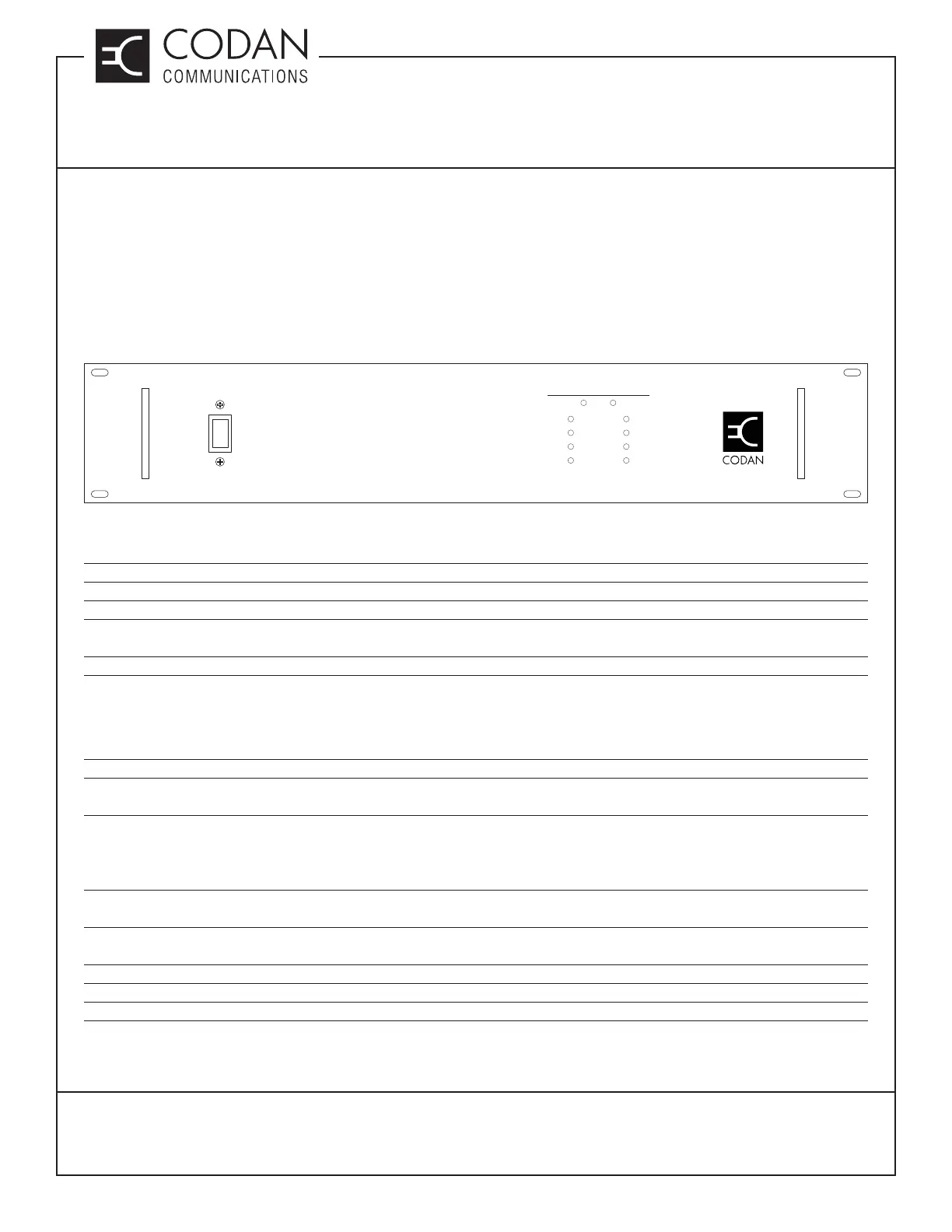
7. Turn the AC switch (located on the front panel) to the ON position to operate the unit.
ON
OFF
SYSTEM STATUS
AC / Input
DC / Output
on
on
on
on
off
off
off
off
Module 1
Module 2
Module 3
Module 4
REDUNDANT POWER SUPPLY