TN835 High Current AC to DC Power Supplies
MT-3/4 Radio Systems
TECHNICAL NOTES
Page 2 of 2
LMRSALES@CODANCOMMS.COM
CODANCOMMS.COMTECHNICAL NOTE:
TN835, REV 1-1-0, © Mar 2013
CANADA/US +1 250 382 8268 | TOLL FREE +1 800 664 4066
Battery Backup
During normal operation, the power supply provides all of the necessary power to the output while fl oat charging
the battery that is connected at the battery backup output. In the event that the AC power source is interrupted, the
battery will start to supply power to the load through an isolation diode; however, the load voltage will be 0.4 Vdc
lower than the battery voltage. The power resistors used to fl oat charge the battery limit the charging current to a
value based on a 100Ah deep cycle battery.
Alarm and Status Signals
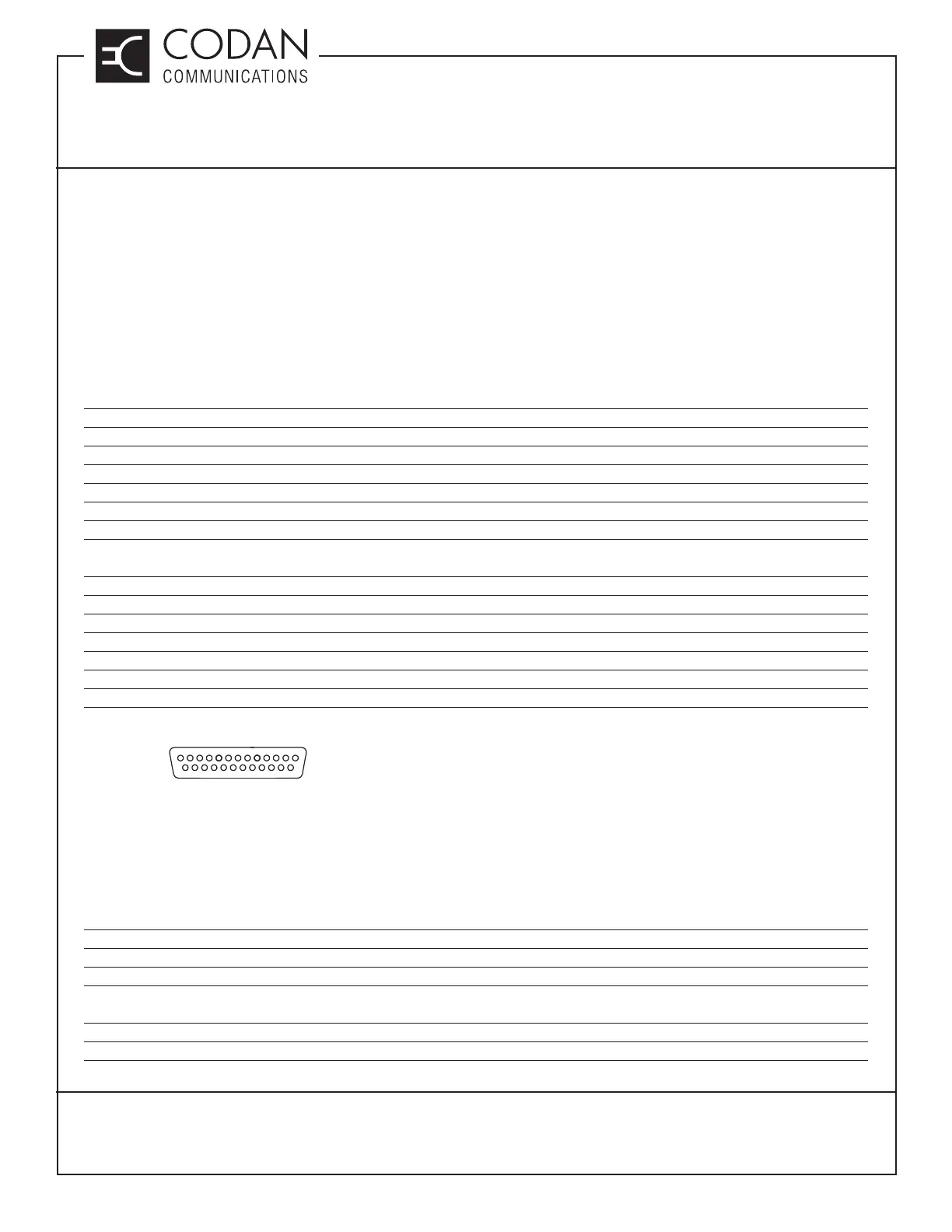
For remote monitoring, the power supply is equipped with a female DB25 connector (on the rear of the power supply
behind a protective panel) that outputs various alarm and status signals such as:
Pin Number Pin Description Voltage Out
Pin 1 AC Good signal +15 Vdc if AC Voltage present / 0 Vdc if AC voltage not available
Pin 2 +5 Vdc reference signal +5 Vdc
Pin 3 No connection N/C
Pin 4 Fan Good signal +5 Vdc if both fans are good / 0 Vdc if one or both fans not functioning
Pin 5 No connection N/C
Pin 6 Current signal System current out analog signal (0 Vdc ~ +5 Vdc)
Pin 7 Module 1 Good signal +5 Vdc If Module is Good
0 Vdc If Module is not functioning or not present
Pin 8 Module 2 Good signal
Pin 9 Module 3 Good signal
Pin 10 Module 4 Good signal
Pin 11 No connection N/C
Pin 12 Temp warning signal +5 Vdc if the temperature inside the unit is over 48°C
Pin 13 System VOUT Signal +13.8 Vdc
Pin 14-15 Ground Ground
Figure 1: Pin Layout of the DB25 Connector
LED Status Display
An LED status indicator (located on the front panel) identifi es how many modules are connected on the board and
are working. The display also shows the status of the AC input and the DC output signals.
The green LED status indicator will be lit when:
• AC line voltage is preset
• DC output voltage is present
• Module voltage is present
The yellow LED status indicator will be lit when:
• Module is not present in the slot
• Module is not producing any output
1
13
25
14