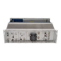
TN441 AMP-4 VHF and UHF 30 Watt Power Amplifi ers
MT-3/4 Radio Systems
TECHNICAL NOTES
Page 2 of 2
LMRSALES@CODANCOMMS.COM
CODANCOMMS.COMTECHNICAL NOTE:
TN441, REV 2-0-0, © Jul 2013
CANADA/US +1 250 382 8268 | TOLL FREE +1 800 664 4066
Power Amplifi er Alignment:
Before aligning the 30 Watt Power Amplifi er, the Transmitter Exciter should be tuned properly following the alignment
procedures in the Technical Notes or Instruction Manual for the transmitter. Disable the output power alarm,
VSWR alarm, and VSWR overload by turning the adjustment pots fully counter clockwise (if applicable, depending
on use and model). Set the RF output power at 6.4 Watts. Do not exceed 8.0 Watts at any time into the power
amplifi er.
Connect the transmitter exciter RF output to the power amplifi er input using the 37 cm cable supplied with the power
amplifi er. Connect the Wattmeter to the power amplifi er output and key the exciter by fl ipping the switch on the front
panel to KEY TX.
If jumper J1 on the amplifi er is set for Local Mode (default), adjust the front panel
PWR CTRL (Power Control) pot to obtain the desired RF output power on the
wattmeter.
If jumper J1 is set for Remote Mode, set the voltage on Pin Z22, on the rear
connector of the power amplifi er, to obtain the desired RF output power on the
wattmeter. Pin Z22 can be accessed on an auxiliary panel on the back of the
subrack. The Remote Power Control Voltage range is 0 to 9.5 Vdc.
Power Amplifi er LEDs and Alarms:
The AMP-4 has a heavy duty and a thermally switched cooling fan. The power amplifi er has three LEDs on the front
panel and three open connector alarm outputs at the rear connector.
The green TX LED illuminates when the power amplifi er is transmitting greater than 20 Watts. When the output
power is less than 20 Watts, the “Low TX Output” open collector alarm on Pin B26 will activate.
The red G/F (General Fault) LED is a combination of two alarms: the heatsink temperature and the supply voltage.
The G/F LED will illuminate in standby mode when the heatsink temperature exceeds 80°C (176°F) and will reset
when the temperature falls below 70°C (158°F).
The G/F LED will illuminate in active mode (transmit) when the supply voltage exceeds +17.8 Vdc and will reset
when the supply voltage is reduced to +17.3 Vdc.
When the G/F LED illuminates, the “General Fault” open collector alarm on Pin B24 will activate, and the power
amplifi er turns off the voltage regulator to the RF and main control circuits to enter a low power mode
The red VSWR LED illuminates when the power amplifi er has a VSWR of 2.1:1 to 4.0:1. When the VSWR LED
illuminates, the “VSWR” open collector alarm on Pin Z26 will activate.
Note: For complete alignment procedures, refer to the instruction manual. These notes are for reference only.
132
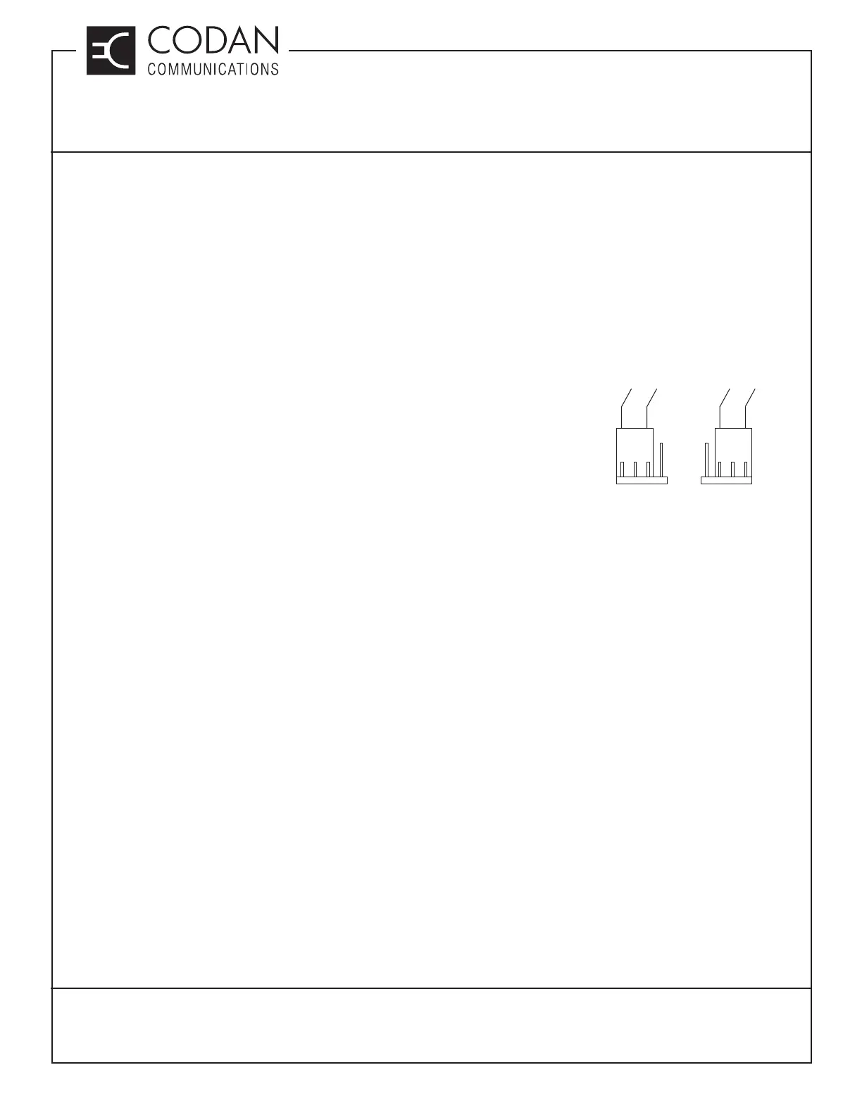
Remote
Power Control
Local
132
or