TN500 SR-39-1 Subrack
MT-3/4 Radio Systems
TECHNICAL NOTES
Page 2 of 4
LMRSALES@CODANCOMMS.COM
CODANCOMMS.COMTECHNICAL NOTE:
TN500, REV 5-0-0, © Aug 2016
CANADA/US +1 250 382 8268 | TOLL FREE +1 800 664 4066
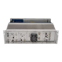
If a VHF or UHF power amplifi er is installed, only one transmitter and receiver pair can be installed since the power
amplifi er takes up two slots, as shown in Figure 3.
Figure 3: Subrack with Power Amplifi er
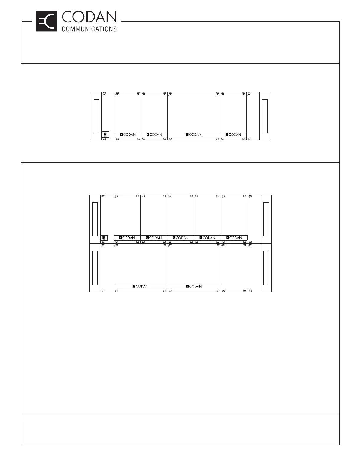
If two transceivers are used with power amplifi ers, the power amplifi ers are normally installed in a second subrack
as shown in Figure 4. This keeps all of the audio and control signal routing to a single subrack, simplifying the
system. A second system regulator and the mulitiple link controller are not required for this confi guration.
Figure 4: Dual Subracks with Two Power Amplifi ers
The 96 pin auxiliary control connector, located on the back of the motherboard (facing rear of the subrack), has 96
pins and provides access to virtually all signal and power lines on the motherboard. Many repeater confi gurations
can be implemented by interconnecting some of these lines through a mating 96 pin connector. Additionally,
external equipment can also be connected to the repeater through the auxiliary control connector, allowing for more
extensive radio control (i.e., DC remotes, tone remotes etc.). Note: The + and - DC lines from the auxiliary control
connector are not fused. Use caution with these lines so that interconnect cables are not overloaded.
DB25 Connector to CI-RC-4M-G2
Connector J12 is a female DB25 connector which can be used for connecting audio, channel select and control
signal lines to a CI-RC-4M-G2 (second generation) multiple link controller. When connecting to a CI-RC-4M-G2, a
standard straight-through male-to-male DB25 cable can be used.
POWER AMPLIFIER
A
SYSTEM
REGULATOR
RECEIVER
A
TRANSMITTER
A
CONTROL
1
OPTIONAL
CONTROL
2
BLANK
PANEL
BLANK
PANEL
SYSTEM
REGULATOR
RECEIVER
B
TRANSMITTER
B
RECEIVER
A
TRANSMITTER
A
CONTROL
1
OPTIONAL
CONTROL
2
POWER AMPLIFIER
B
BLANK
PANEL
POWER AMPLIFIER
A