IGS-NT-BC, SW Version 1.2.0, ©ComAp – January 2019
IGS-NT-BC-1.2.0 Reference Guide.PDF
Modbus Switches
The “Modbus Switches” contains of two groups of LBOs named “ModbusSw1” and “ModbusSw2”. Both
registers are available on Modbus for simple writing (using command 6 or 16). The particular bits of these
registers are available as binary status for universal use in logical binary outputs of the controller as
“ModbusSw1..ModbusSw32”. No password is required for writing of those registers. There are two Values
“ModbusSw1” and “ModbusSw2” in group “Log Bout” available for back-reading.
NOTE:
The LSB of ModbusSw1 (46337) corresponds with LBO “ModbusSw1”
The LSB of ModbusSw2 (46338) corresponds with LBO “ModbusSw17”
The Values ModbusSw1 and ModbusSw2 have the position of LSB opposite-wise.
Examples:
Register port for writing
LBO ModbusSw16 ………………….ModbusSw1
Register port for writing
LBO ModbusSw32 ………………….ModbusSw17
Analog Input Sensors and User Sensors
Controller and/or some extension modules allow connection of sensor outputs to Analog Inputs. There is
whole variety of common sensor output characteristics prepared in configuration by default. Although if there
is sensor that is not in the list, it is possible to prepare custom characteristics (up to 16) with up to 31
definition points.
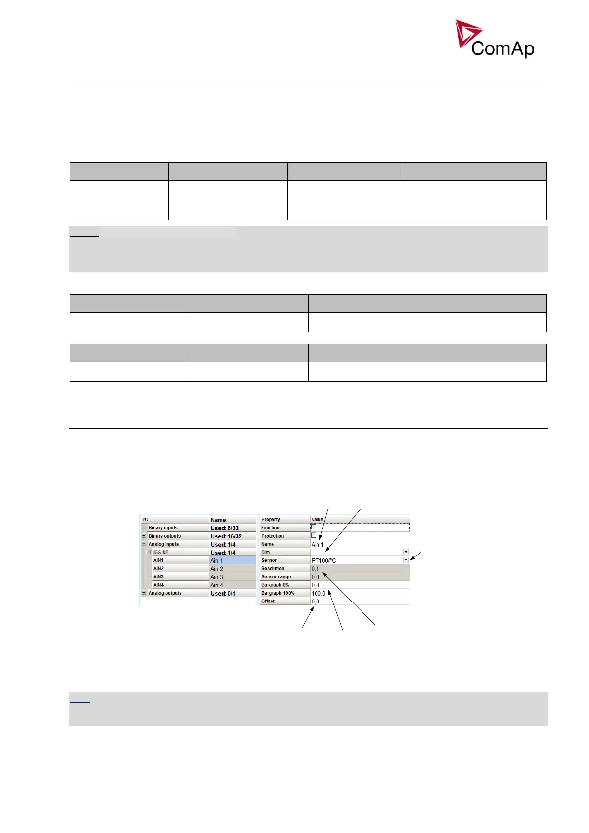
Name of the
Analog Input
Dimension
Connected Sensor
(default and user
sensors)
Resolution and Range of the sensor (in
some cases this is fixed by sensor type
and cannot be changed)
Interpretation of
the received value
in bar graph form
Offset of the
received value
Figure: Sensor adjustment in GenConfig
Default sensors: PT100/°C, PT1000/°C, NI1000/°C, PT100/°F, PT1000/°F, NI1000/°F,
4-20mA active, 0-2400ohm, 0-2.4V, Tristate
HINT
There is “electronic” type of sensor available for Shared Analog Inputs which can be used to interpret shared
data over CAN bus.