EasyManuals Logo

ComAp IG-NTC GC User Manual

ComAp IG-NTC GC
260 pages
To Next Page IconTo Next Page
To Previous Page IconTo Previous Page
Page #16 background imageLoading...
Page #16 background image
IGS-NT-BC, SW Version 1.2.0, ©ComAp January 2019
IGS-NT-BC-1.2.0 Reference Guide.PDF
16
(1)
EXTENSIO N
M OD ULES
INTERC ONTR OLLER
& M ON ITORI NG
DISPLAY
L H L H
IS-NT
LB 9
BANK
CONTROLLER
k
L2
L3
GENERATOR VOLTAGE
MAINS VOLTAGE
L1
L2
L3
TO OTHER GENSET
BANKS
COMMON BUSBAR
BANK BUSBAR
TO THE GENSETS
GENERATOR CURRENT
l
L1 L2 L3
k
l
K
L
L1
OPTIONAL CT
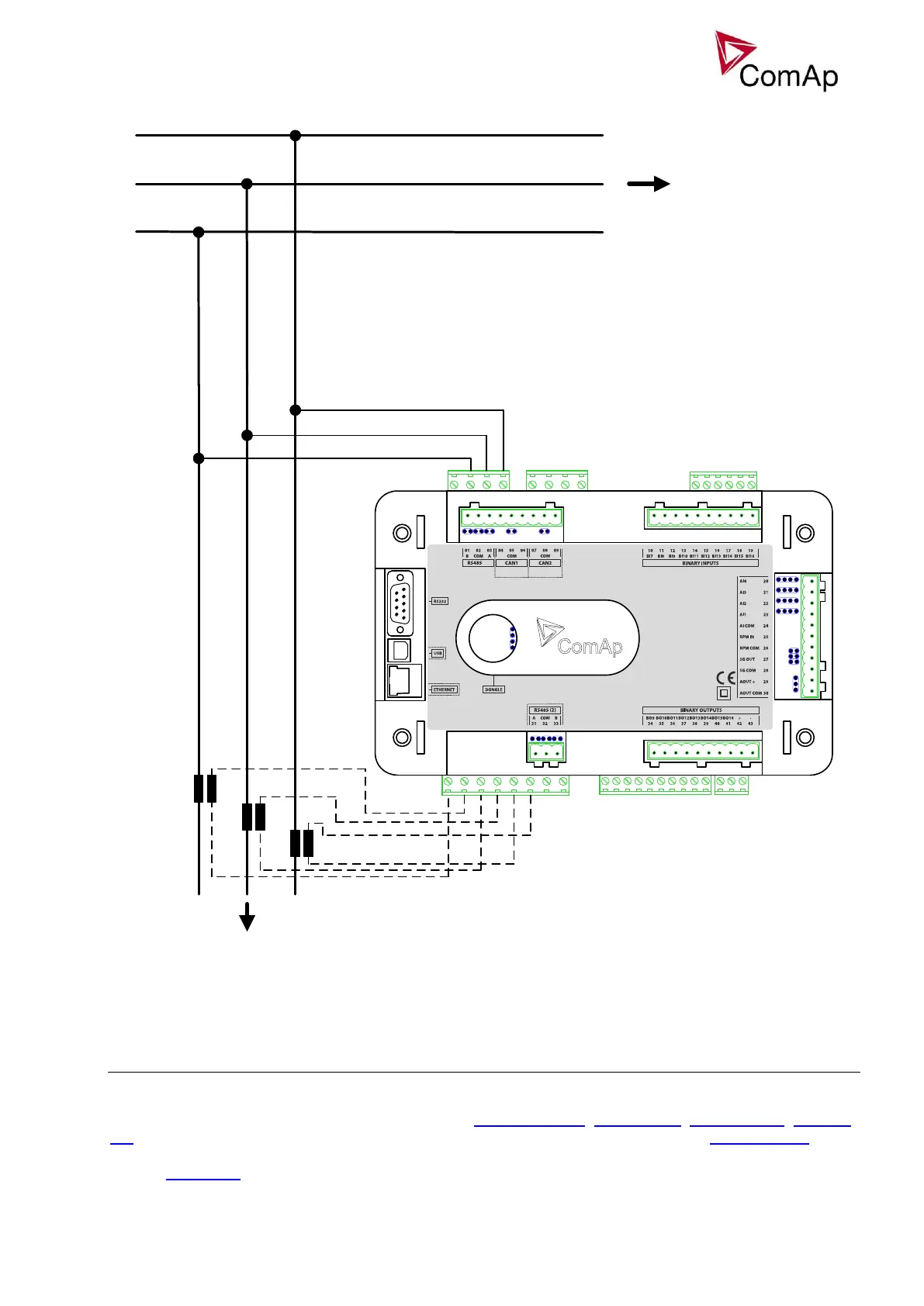
Figure: AC measurement without the BCB
Note: It is recommended to use T1A fuses for controller voltage measurement circuits protection.
BCB control and synchronizing
If the system is equipped with BCB the BCB is controlled by the Bank controller. There is a set of control
outputs for various types of the breaker or contactor: BCB close/open, BCB ON coil, BCB OFF coil, BCB UV
coil. Breaker feedback signal is to be connected to the binary input with logical function BCB feedback. If this
logical function is not configured on any binary input the bank controller assumes BCB is not used. See the
chapter Installation for information about proper wiring of the site with or without BCB.

Table of Contents

Questions and Answers:

Question and Answer IconNeed help?

Do you have a question about the ComAp IG-NTC GC and is the answer not in the manual?

ComAp IG-NTC GC Specifications

General IconGeneral
BrandComAp
ModelIG-NTC GC
CategoryController
LanguageEnglish

Related product manuals