IGS-NT Installation Guide
G
I1k I1l I3k I3lI2k I2l
K L
k l
L1
L2
L3
N
Ink Inl
K L
k l
K L
k l
L K
l k
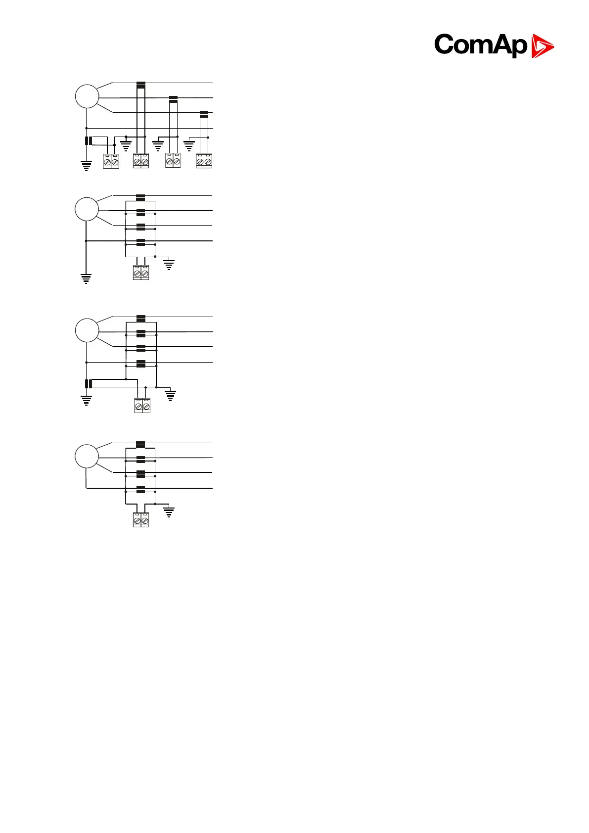
The simplest arrangement covers all zones from the
generator windings to the final circuits in the load
network.
G
L1
L2
L3
N
Ink Inl
k l
k l
k l
k l
This arrangement covers earth faults in the load
network only.
G
L1
L2
L3
N
Ink Inl
L K
l k
k l
k l
k l
k l
K L
This arrangement necessary for restricted earth fault
protection. The location of the neutral earthing point in
relation to the protection current transformers in the
neutral conductor determines whether four or five
current transformers are employed.
G
L1
L2
L3
N
Ink Inl
k l
k l
k l
k l
This arrangement necessary for restricted earth fault
protection. The location of the neutral earthing point in
relation to the protection current transformers in the
neutral conductor determines whether four or five
current transformers are employed.
 Loading...