Basic Information
20
C2500CB-OM-EN-16
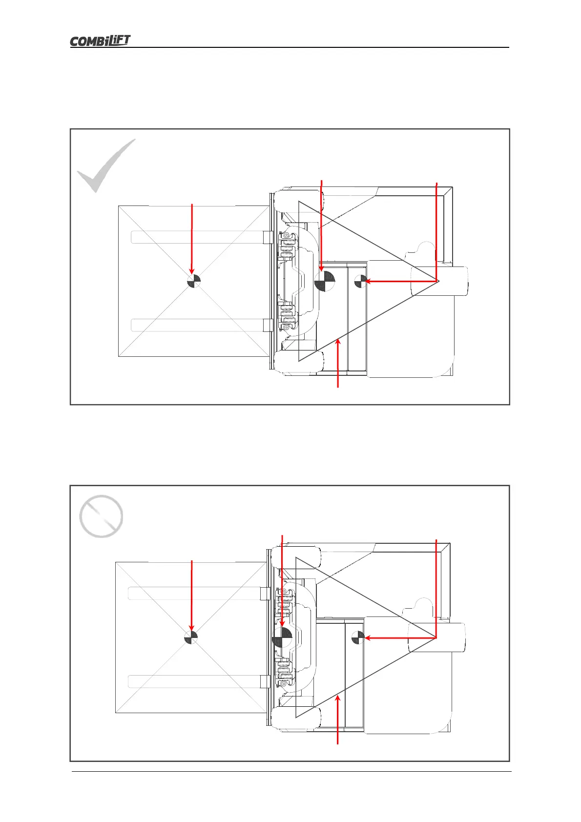
The diagram below illustrates the truck with a uniform load less than the maximum
rated capacity resting on the forks. In this case the combined centre of gravity lies
inside the boundary of the stability triangle, therefore the truck and load will remain
stable.
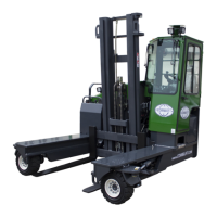
The diagram below illustrates the truck with a uniform load greater than the maximum
rated capacity resting on the forks. In this case the combined centre of gravity lies
outside the boundary of the stability triangle, therefore the truck and load will be
unstable and a tip-over is likely to occur.
Combi-CB & Load
Combined
Centre of Gravity
Load
Centre of Gravity
Combi-CB
Centre of Gravity
Stability Triangle Boundary
Combi-CB & Load
Combined
Centre of Gravity
Load
Centre of Gravity
Combi-CB
Centre of Gravity
Stability Triangle Boundary