Components & Controls
32
C2500CB-OM-EN-16
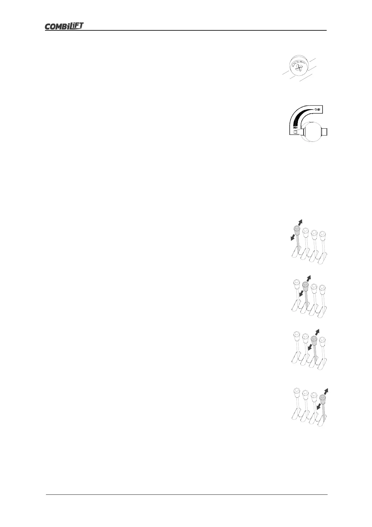
Heater Fan Switch (If Fitted)
This is a four position rotary switch located on the control
panel (if fitted).
It is used to switch the heater fan on and to control the fan
speed.
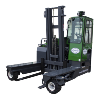
Heater Air Temperature Control (If Fitted)
The heater air temperature control is located beside the
seat belt to the right hand side of the operators seat.
To increase the temperature of the air expelled from the air
vents (if fitted) turn the knob anti-clockwise.
To decrease the temperature of the air expelled from the air
vents (if fitted) turn the knob clockwise.
3.3 Hydraulic Lever Operation
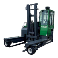
Lift/Lower Lever (on left)
The lift/lower lever controls the upward and downward
movement of the mast and forks.
To raise the forks, PULL the lever BACK
To lower the forks, PUSH the lever FORWARD
Tilt Lever (2
nd
from left)
The mast tilt lever controls the tilt angle of the mast and
forks.
To tilt the mast back, PULL the lever BACK.
To tilt the mast forward, PUSH the lever FORWARD
Side Shift Lever (3
rd
from left)
The side shift lever controls the lateral movement of the
forks.
To move the forks to the right, PULL the lever BACK.
To move the forks to the left, PUSH the lever FORWARD.
Optional Auxiliary Function Lever (4
th
from left)
The auxiliary function lever controls auxiliary hydraulic
functions.
Trucks with more than one auxiliary function may have a
push button fitted on the fourth lever.
Operators must acquaint themselves with the operation of
any auxiliary functions before using the truck.
The most common auxiliary function fitted is hydraulic fork
positioning.