22
5. MOUNTING AND WIRING
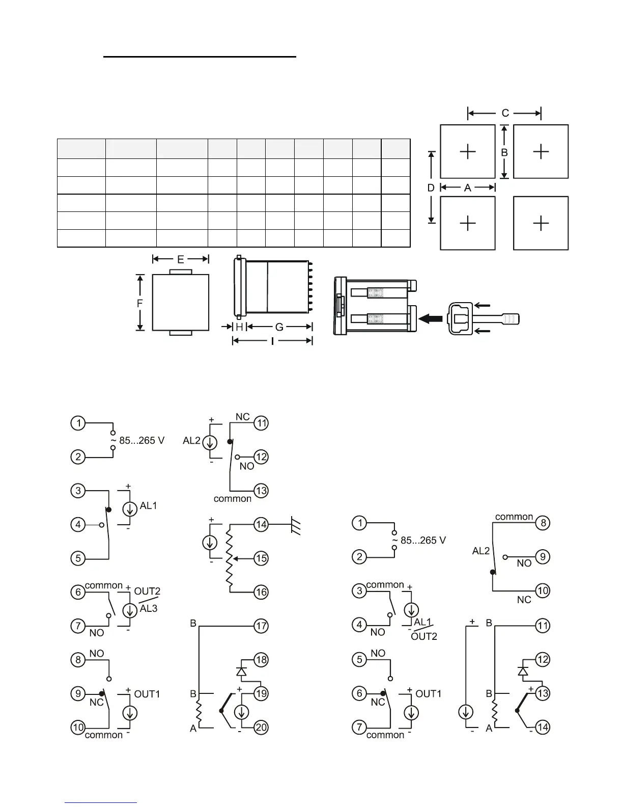
5.1. Mounting
The controller overall dimensions, recommended panel cut-outs
and controller-to-controller minimum clearance for the different case types
are given in the table below.
Case
A B C D E F G H I
'S'
44.5
+0.5
44.5
+0.5
65 70 50 50 81 14 95
'V'
44.5
+0.5
90.5
+0.5
65 116 50 96 81 14 95
'H'
90.5
+0.5
44.5
+0.5
111 70 96 50 81 14 95
'B'
90.5
+0.5
90.5
+0.5
111 116 96 96 81 14 95
'Q'
68.5
+0.5
68.5
+0.5
89 94 74 74 81 14 95
5.2. Wiring
The wiring diagrams showing input, output, and power supply connections for the different case types
are given below. The cold junction temperature compensation sensor is represented by diode symbol.
RT1800-H/V/B RT1800-Q