5
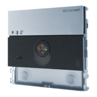
Art. UT1010VC
18.
UP
13. 14. 15.3. 4. 5. 6. 7.
9.10.11.
12.
8.
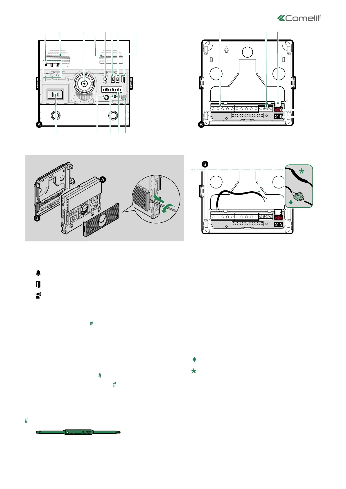
1. 2. 2.
16.
17.
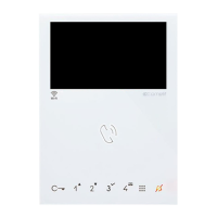
1. Indicator LEDs
call sent (green) / system busy (red)
lock-release enabled
communication enabled
2. Loudspeakers
3. Colour video camera (with Art. UT1020 only)
4. Speaker volume control
5. S1 Button programming selector
6. S2 Special programming selector
7. Micro USB input for programming via computer
8. Twilight sensor
9. Addressing and programming Dip Switches
10. Microphone volume control
11. Programming confirmation button
12. Digital microphone
Use screwdriver supplied
13. Terminal block for connection:
RTE programmable RTE (local lock-release
input) or DO input (door open indication)
GND RTE or DO input reference negative
IF door lock reference negative
NO NC COM relay contacts
V- V+ power supply
LL bus line connection
14. Ethernet terminal block, only for use in case of additional
modules with LAN
15. Connector for additional modules with LAN
16. 17. Connector for additional module connection
18. Remote camera connection (with Art. UT1010VC only):
in flush-mounted installations, use the terminal;
in surface-mounted installations, solder the wires
and use the heat-shrink sheath.