20
Chest 5 C5 White/black V5 Brown/orange
Chest 6 C6 White/violet V6 Brown/violet
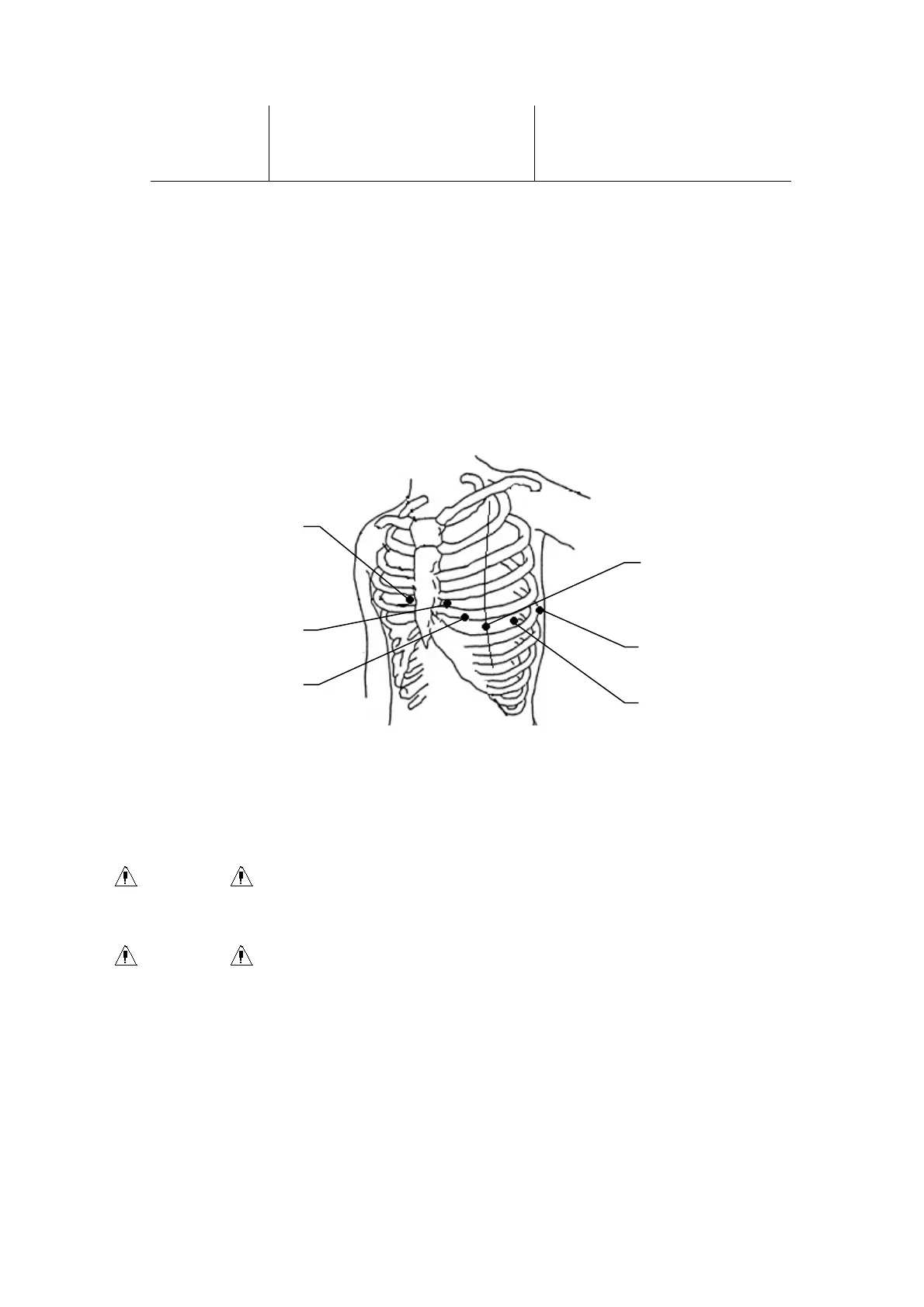
As the following figure shows, the chest electrodes’ position on body surface is
C1: Fourth intercostals space at right border of sternum
C2: Fourth intercostals space at left border of sternum
C3: Fifth rib between C2 and C4
C4: Fifth intercostals space on left midclavicular line
C5: Left anterior axillary line at the horizontal level of C4
C6: Left midaxillary line at the horizontal level of C4
The contacting resistance between the patient and the electrode will affect the quality of ECG
greatly. In order to get a high-quality ECG, the skin/electrode resistance must be minimized
while connecting electrodes.
WARNING : Be sure that all electrodes have been connected to the patient correctly
before operation.
WARNING : Be sure that the conductive parts of electrodes and associated connectors,
including neutral electrode, should not contact with earth or any other
conducting objects.
Chest electrodes connection:
1) Ensure the electrodes to be clean firstly;
2) Align all lead wires of patient cable to avoid twisting, and connect the associated
electrode connectors with corresponding electrodes according to the color and
identifier;
C6
C1
C2
C5
C4
C3