F80CTL & G80CTL: Installation, Start–Up, Operating and Service and Maintenance Instructions
Manufacturer reserves the right to change, at any time, specifications and designs without notice and without obligations.
16
A95236
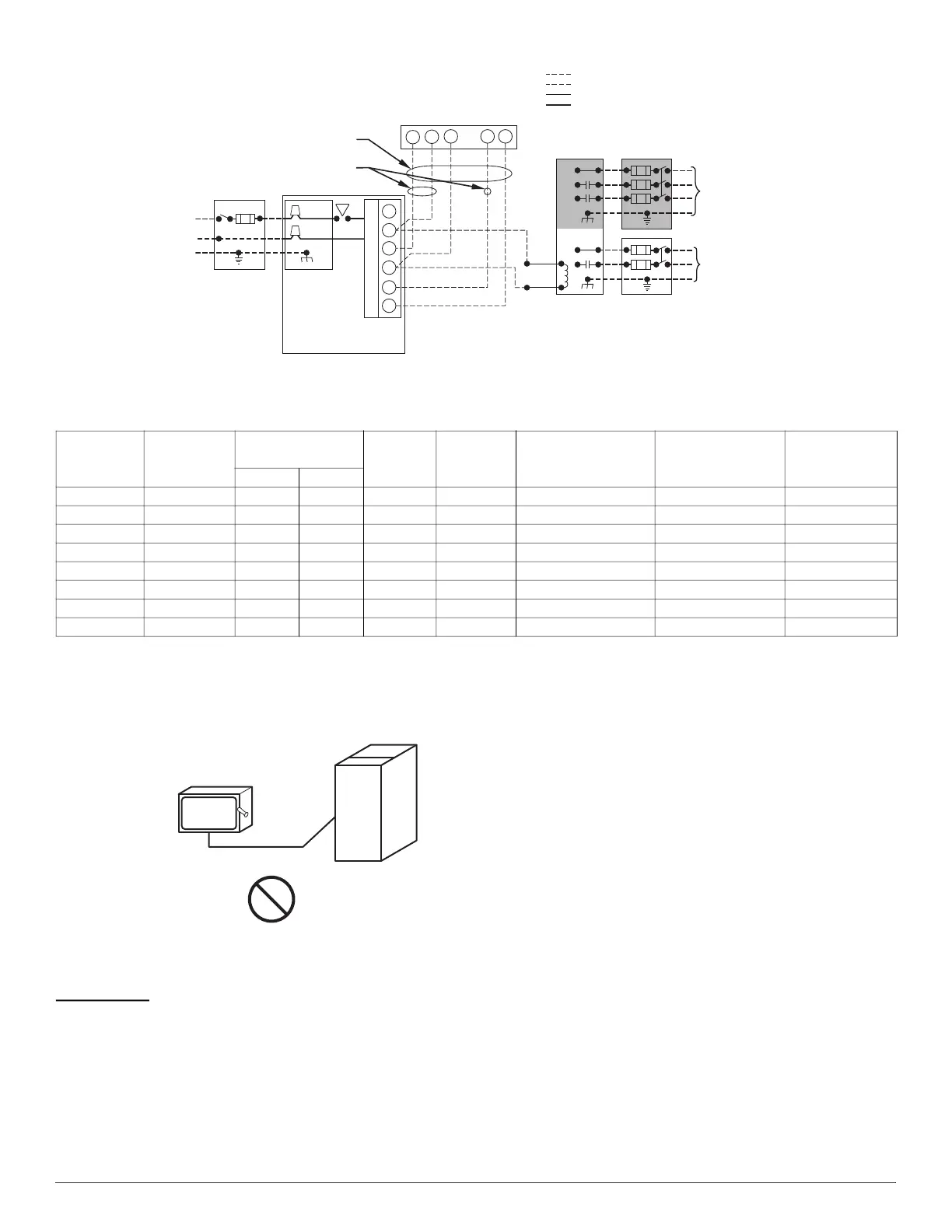
Fig. 24 – Field Wiring Diagram
A190279
Fig. 25 – Field-Supplied External
Electrical Box on Furnace Casing
115-V Wiring
Verify that the voltage, frequency, and phase correspond to that specified
on unit rating plate. Also, check to be sure that service provided by
utility is sufficient to handle load imposed by this equipment. Refer to
rating plate or Table 5 for equipment electrical specifications.
U.S. Installations: Make all electrical connections in accordance with
National Electrical Code (NEC) NFPA 70 and any local codes or
ordinances that might apply.
Use a separate, fused branch electrical circuit with a properly sized fuse
or circuit breaker for this furnace. See Table 5 for wire size and fuse
specifications. A readily accessible means of electrical disconnect must
be located within sight of the furnace.
NOTE: Proper polarity must be maintained for 115-v wiring. If polarity
is incorrect, control LED status indicator light will flash status code 10
and furnace will NOT operate.
J-BOX RELOCATION
NOTE: If factory location of J-Box is acceptable, go to next section
(ELECTRICAL CONNECTION to J-Box).
NOTE: On 14-in. (356 mm) wide casing models, the J-Box shall not be
relocated to other side of furnace casing when the vent pipe is routed
within the casing.
1. Remove and save two screws holding J-Box, see Fig. 26.
NOTE: The J-Box cover need not be removed from the J-Box in order
to move the J-Box. Do NOT remove green ground screw inside J-Box,
see Fig. 26.
2. Cut wire tie on loop in furnace wires attached to J-Box.
3. Move J-Box to desired location.
4. Fasten J-Box to casing with the two screws removed in Step 1.
5. Route J-Box wires within furnace away from sharp edges, rotating
parts and hot surfaces.
Table 5 – Electrical Data
FURNACE
SIZE
VOLTS-
HERTZ-
PHASE
OPERATING
VOLTAGE RANGE
*
*. Permissible limits of the voltage range at which the unit operates satisfactorily.
MAX.
UNIT
AMPS
UNIT
AMPACITY
†
†. Unit ampacity = 125 percent of largest operating component’s full load amps plus 100 percent of all other potential operating components’ (EAC, humidifier, etc.) full load
amps.
MAX. WIRE LENGTH
- FT (M)
‡
‡. Length shown is as measured 1 way along wire path between furnace and service panel for maximum 2 percent voltage drop.
MAX. FUSE OR CKT
BKR AMPS
**
**. Time-delay type is recommended.
MIN. WIRE
GAUGE
Max. Min.
0451712 115-60-1 127 104 9.0 12.0 30 (9.4) 15 14
0701412 115-60-1 127 104 9.0 12.0 30 (9.4) 15 14
0701716 115-60-1 127 104 9.0 13.0 28 (8.7) 15 14
0702120
115-60-1 127 104 14.1 18.4 31 (9.5) 20 12
0901716
115-60-1 127 104 9.6 12.63 29 (9.0) 15 14
0902120
115-60-1 127 104 14.7 19.0 30 (9.2) 20 12
1102120 115-60-1 127 104 15.0 19.3 29 (9.1) 20 12
1352422
115-60-1 127 104 15.0 19.3 29 (9.1) 20 12
115-VOLT FIELD-
SUPPLIED
FUSED
DISCONNECT
JUNCTION
BOX
CONTROL
BOX
24-VOLT
TERMINAL
BLOCK
THREE-WIRE
HEATING-
ONLY
FIVE
WIRE
NOTE 2
NOTE 1
1-STAGE
THERMOSTAT
TERMINALS
FIELD-SUPPLIED
FUSED DISCONNECT
CONDENSING
UNIT
FURNACE
COM
R
WCY RG
GND
GND
FIELD 115-, 208/230-, 460-VOLT WIRING
FACTORY 24-VOLT WIRING
FACTORY 115-VOLT WIRING
Connect Y/Y2-terminal as shown for proper operation.
Some thermostats require a "C" terminal connection as shown.
If any of the original wire, as supplied, must be replaced, use
same type or equivalent wire.
208/230- O
460-VOLT
THREE
PHASE
208/230-
VOLT
SINGLE
PHASE
HT
BLK
WHT
BLK
W/W1
W2
Y/Y2
G
NOTES: 1.
2.
3.
COPPER
WIRE ONLY
ELECTRIC
DISCONNECT
SWITCH
ALUMINUM
WIRE