F80CTL & G80CTL: Installation, Start–Up, Operating and Service and Maintenance Instructions
Manufacturer reserves the right to change, at any time, specifications and designs without notice and without obligations.
41
c. Pressure switches.
d. Limit overtemperature switch.
e. Gas valve.
f. Hot surface igniter.
g. Flame-sensing electrode.
h. Flame rollout switches.
6. Remove screws that fasten the collector box assembly to the cell
panel. Be careful not to damage the collector box. Inducer assembly
and elbow need not be removed from collector box.
7. Disconnect gas line from gas manifold.
8. Remove the four screws that attach the burner assembly to the cell
panel. The gas valve and individual burners need not be removed
from support assembly. Remove NOx baffles, if installed.
NOTE: Be very careful when removing burner assembly to avoid
breaking igniter. See Fig. 50and Fig. 51 for correct igniter location.
A05026
Fig. 50 – Igniter Position - Top View
A05025
Fig. 51 – Igniter Position - Side View
NOTE: The materials needed in Step 9 can usually be purchased at local
hardware stores.
9. Using a field-provided 25-caliber rifle cleaning brush; a 36-in. (914
mm) long, 1/4-in. (6 mm) diameter steel spring cable; and a
variable speed drill, do the following:
a. Remove metal screw fitting from wire brush to allow insertion
into cable.
b. Insert the twisted wire end of brush into end of spring cable, and
crimp tight with crimping tool or crimp by striking with
ball-peen hammer. TIGHTNESS IS VERY IMPORTANT. After
crimping:
(1.) Attach variable-speed, reversible drill to the end of spring
cable (end opposite brush).
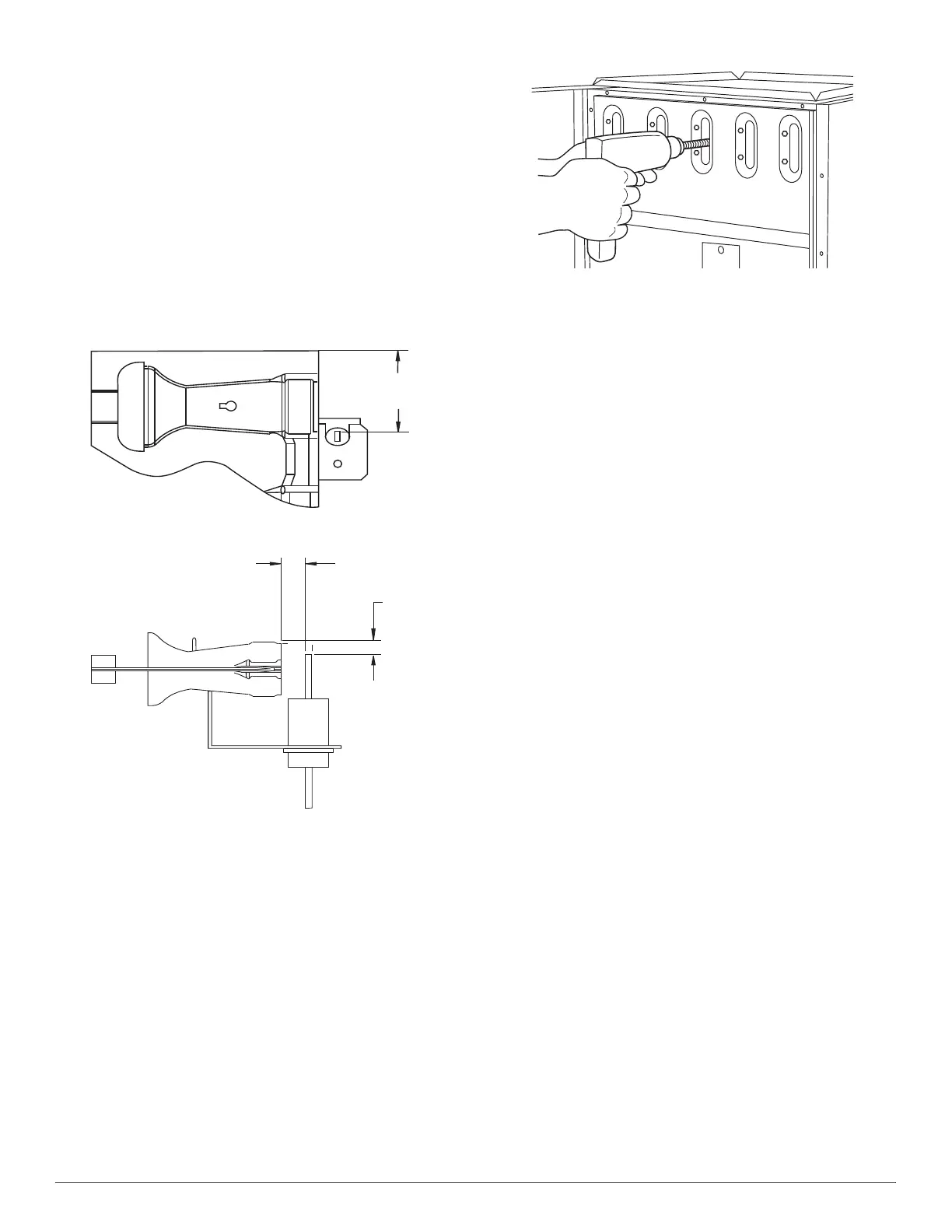
(2.) Insert brush end of cable into the outlet opening of cell and
slowly rotate with drill, see Fig. 52. DO NOT force cable.
Gradually insert cable into upper pass of cell.
A91252
Fig. 52 – Cleaning Heat Exchanger Cell
(3.) Work cable in and out of cell 3 or 4 times to obtain
sufficient cleaning. DO NOT pull cable with great force.
Reverse drill and gradually work cable out.
(4.) Insert brush end of cable in burner inlet opening of cell, and
proceed to clean 2 lower passes of cell in same manner as
upper pass.
(5.) Repeat foregoing procedures until each cell in furnace has
been cleaned.
(6.) Using vacuum cleaner, remove residue from each cell.
(7.) Using vacuum cleaner with soft brush attachment, clean
burner assembly.
(8.) Clean flame sensor with fine steel wool.
(9.) Install NOx baffles (if removed).
(10.)Reinstall burner assembly. Center burners in cell openings.
10. Remove old sealant from cell panel and collector box flange.
11. Spray releasing agent on the heat exchanger cell panel where
collector box assembly contacts cell panel.
NOTE: A releasing agent such as cooking spray or equivalent (must not
contain corn or canola oil, aromatic or halogenated hydrocarbons or
inadequate seal may occur) and RTV sealant (G.E. 162, 6702, or
Dow-Corning 738) are needed before starting installation. DO NOT
substitute any other type of RTV sealant.
12. Apply new sealant to flange of collector box and attach to cell panel
using existing screws, making sure all screws are secure.
13. Reconnect wires to the following components (Use connection
diagram on wiring label, if wires were not marked for reconnection
locations.):
a. Draft safeguard switch.
b. Inducer motor.
c. Pressure switches.
d. Limit overtemperature switch.
e. Gas valve.
f. Hot surface igniter.
g. Flame-sensing electrode.
h. Flame rollout switches.
14. Reinstall internal vent pipe, if applicable.
15. Reinstall vent connector on furnace vent elbow. Securely fasten
vent connector to vent elbow with 2 field-supplied,
corrosion-resistant, sheet metal screws located 180° apart.
16. Replace blower access door only if it was removed.
17. Set thermostat above room temperature and check furnace for
proper operation.
18. Verify blower airflow and speed changes between heating and
cooling.