F80CTL & G80CTL: Installation, Start–Up, Operating and Service and Maintenance Instructions
Manufacturer reserves the right to change, at any time, specifications and designs without notice and without obligations.
2
A190045
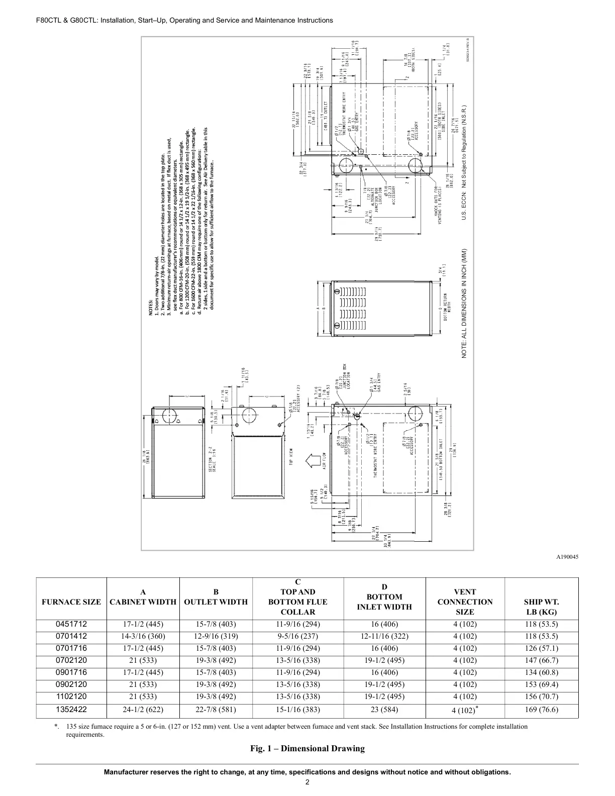
Fig. 1 – Dimensional Drawing
FURNACE SIZE
A
CABINET WIDTH
B
OUTLET WIDTH
C
TOP AND
BOTTOM FLUE
COLLAR
D
BOTTOM
INLET WIDTH
VENT
CONNECTION
SIZE
SHIP WT.
LB (KG)
0451712 17-1/2 (445) 15-7/8 (403) 11-9/16 (294) 16 (406) 4 (102) 118 (53.5)
0701412 14-3/16 (360) 12-9/16 (319) 9-5/16 (237) 12-11/16 (322) 4 (102) 118 (53.5)
0701716 17-1/2 (445) 15-7/8 (403) 11-9/16 (294) 16 (406) 4 (102) 126 (57.1)
0702120 21 (533) 19-3/8 (492) 13-5/16 (338) 19-1/2 (495) 4 (102) 147 (66.7)
0901716 17-1/2 (445) 15-7/8 (403) 11-9/16 (294) 16 (406) 4 (102) 134 (60.8)
0902120 21 (533) 19-3/8 (492) 13-5/16 (338) 19-1/2 (495) 4 (102) 153 (69.4)
1102120 21 (533) 19-3/8 (492) 13-5/16 (338) 19-1/2 (495) 4 (102) 156 (70.7)
1352422 24-1/2 (622) 22-7/8 (581) 15-1/16 (383) 23 (584)
4 (102)
*
*. 135 size furnace require a 5 or 6-in. (127 or 152 mm) vent. Use a vent adapter between furnace and vent stack. See Installation Instructions for complete installation
requirements.
169 (76.6)
U.S. ECCN: Not Subject to Regulation (N.S.R.)
SD5523-4 REV. B
NOTE: ALL DIMENSIONS IN INCH (MM)