F80CTL & G80CTL: Installation, Start–Up, Operating and Service and Maintenance Instructions
Manufacturer reserves the right to change, at any time, specifications and designs without notice and without obligations.
18
L09F025
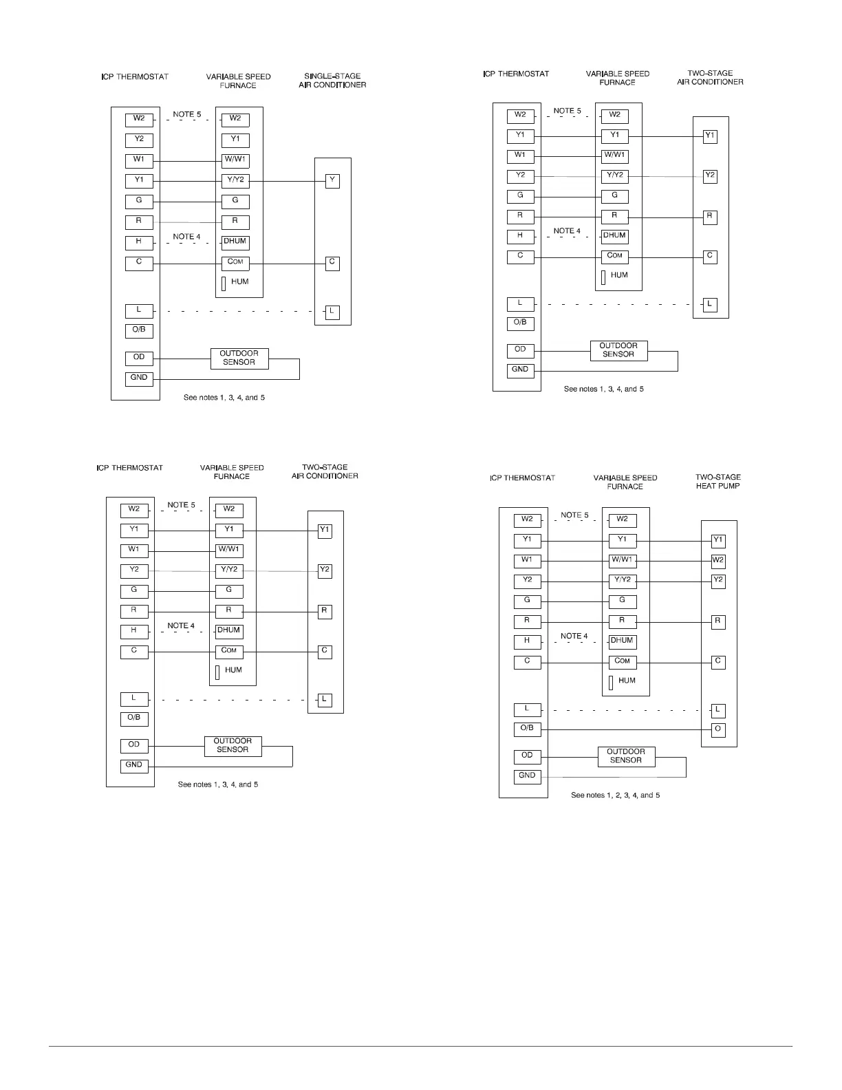
Fig. 28 – Variable Furnace with Single-Speed Air Conditioner
L09F026
Fig. 29 – Variable Furnace with Two-Speed Air Conditioner
L09F026
Fig. 30 – Variable Furnace with Single-Speed Heat Pump
(Dual Fuel)
L09F028
Fig. 31 – Variable Furnace with Two-Speed Heat Pump
(Dual Fuel)
NOTES FOR FIGURE 28 - FIGURE 31
1. Refer to outdoor equipment Installation Instructions for additional information and setup procedure.
2. Outdoor Air Temperature Sensor must be attached in all dual fuel applications.
3. Refer to ICP thermostat Installation Instructions for additional information and setup procedure.
4. When using a Humidity Sensing Thermostat, set DEHUMIDIFY OPTIONS to H DE-ENRGZD FOR DEHUM.
5. Optional connection. If wire is connected SW1-2 on VS furnace control should be set in ON position to allow
ICP Thermostat to control the furnace staging.
6. HUM connection is 24 VAC and is energized when the blower turns on during a call for heat.
7. When connecting 115 VAC to humidifier use a separate 115 VAC supply.
8. When using a humidifier on a HP installation connect humidifier to
hot water.