1541 CIRCUIT THEORY
Read Amplifier Circuits
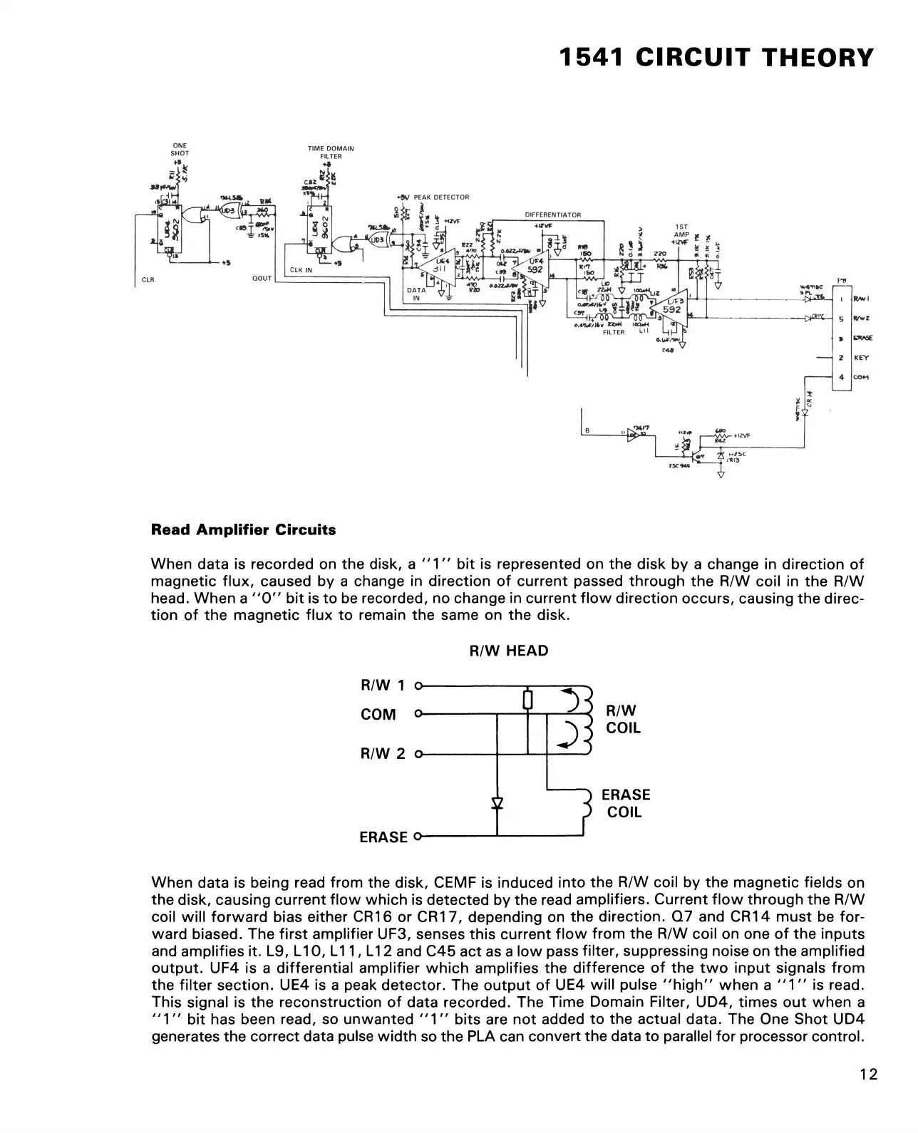
When data is recorded on the disk, a "1" bit is represented on the disk by a change in direction of
magnetic flux, caused by a change in direction of current passed through the R/W coil in the R/W
head. When a "0 " bit is to be recorded, no change in current flow direction occurs, causing the direc
tion of the magnetic flux to remain the same on the disk.
R/W HEAD
R/W
COIL
ERASE
COIL
When data is being read from the disk, CEMF is induced into the R/W coil by the magnetic fields on
the disk, causing current flow which is detected by the read amplifiers. Current flow through the R/W
coil will forward bias either CR16 or CR17, depending on the direction. Q7 and CRM must be for
ward biased. The first amplifier UF3, senses this current flow from the R/W coil on one of the inputs
and amplifies it. L9, L10, L11, L12 and C45 act as a low pass filter, suppressing noise on the amplified
output. UF4 is a differential amplifier which amplifies the difference of the two input signals from
the filter section. UE4 is a peak detector. The output of UE4 will pulse "high” when a "1 " is read.
This signal is the reconstruction of data recorded. The Time Domain Filter, UD4, times out when a
"1" bit has been read, so unwanted "1" bits are not added to the actual data. The One Shot UD4
generates the correct data pulse width so the PLA can convert the data to parallel for processor control.
12