OVERVIEW
The drive is itself an independent memory device. The drive is composed of a media clamp rotating
mechanism, a head positioning mechanism and an eject mechanism. All positioning operations, ex
cluding insertion and removal of the diskette, are controlled by the internal guide mechanism. Closing
the front door causes the media clamp mechanism to operate. Two operations are performed in the
following order:
a) The diskette is centered.
b) The diskette is clamped and retained between the spindle and the hub.
The spindle and hub rotate at 300 r.p.m. through a closed-loop control circuit employing a D.C.
motor/tachometer. It is important that the relationship between the head and the media is maintained
correctly during operation. For this purpose, a pressure pad is used to hold and press down the media
(about 12g) from the opposite side of the head. This head assembly is coupled by a metal band to
a four phase stepping motor which performs the track positioning. One step of the stepping motor
corresponds to a 1 /2 track movement. The control circuit on the logic board selects the direction and
number of steps to the desired track.
The Read/Write head uses a glass-bonded, ferrite/ceramic head. Track-to-track erasing is accomplish
ed by the straddle erase method. The surface of the Read/Write head is mirror-ground to minimize
wear of the head and media. Also, the head is designed in such a way that the maximum signal can
be obtained from the media surface.
The spindle drive motor operates on 12 VDC and turns the spindle, through a belt drive, at 300
revolutions per minute. The speed of the drive motor is controlled by a feedback signal from a
tachometer, which is housed in the drive motor assembly. The feedback signal controls a servo amp
that supplies the 1 2 VDC drive current.
FLASH CODE
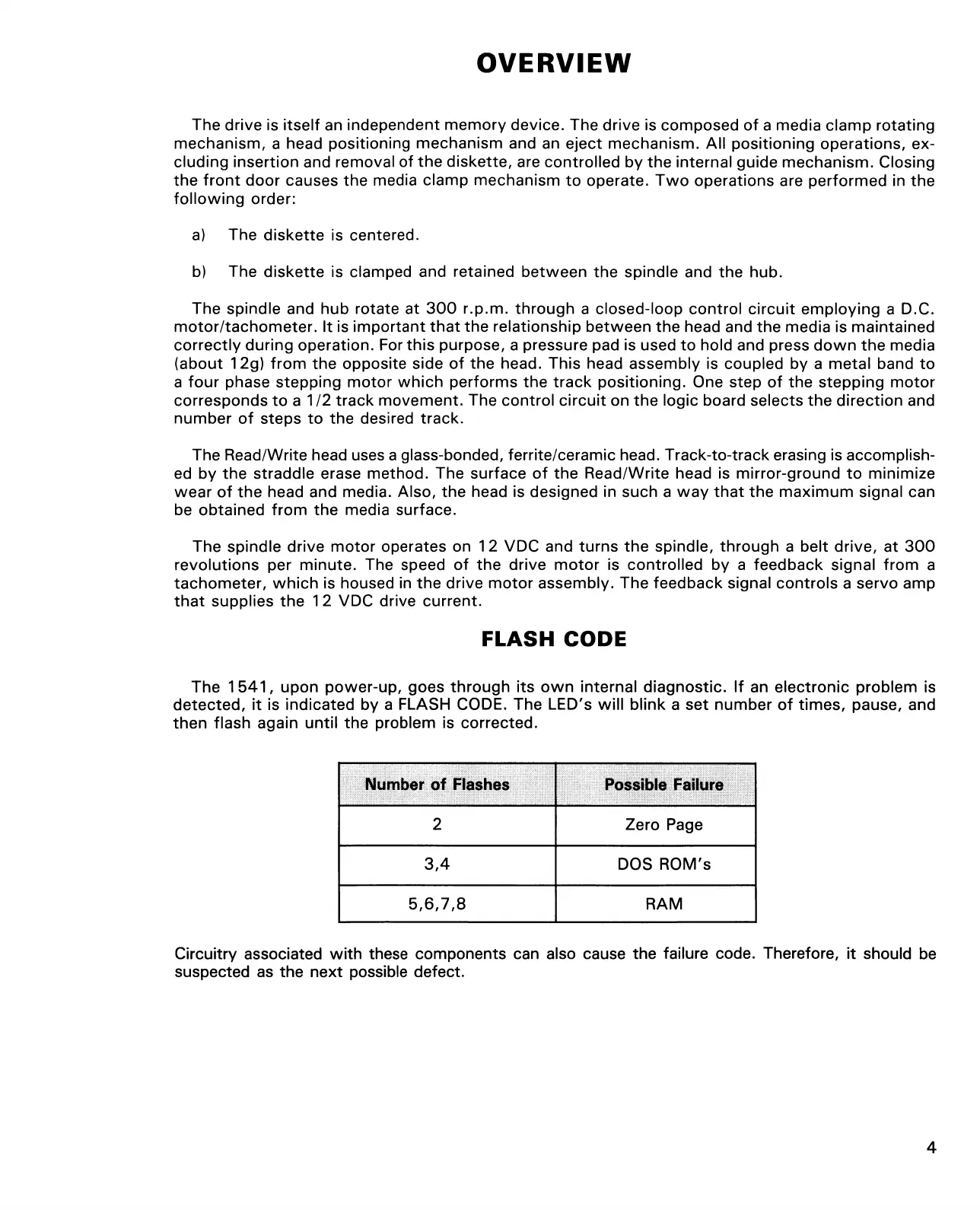
The 1541, upon power-up, goes through its own internal diagnostic. If an electronic problem is
detected, it is indicated by a FLASH CODE. The LED's will blink a set number of times, pause, and
then flash again until the problem is corrected.
Number of Flashes
Possible Failure
2
Zero Page
3,4
DOS ROM's
5,6,7, 8 RAM
Circuitry associated with these components can also cause the failure code. Therefore, it should be
suspected as the next possible defect.
4