1541 CIRCUIT THEORY
Stepper Motor Control Circuits
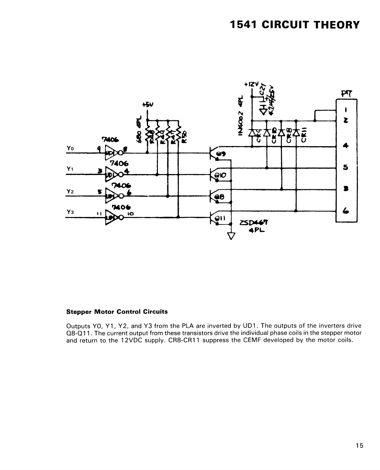
Outputs YO, Y1, Y2, and Y3 from the PLA are inverted by UD1. The outputs of the inverters drive
Q8-Q11. The current output from these transistors drive the individual phase coils in the stepper motor
and return to the 1 2VDC supply. CR8-CR11 suppress the CEMF developed by the motor coils.
15