ADCP-90-545 • Issue 4 • July 2016
Page 32
© 2016 CommScope. All Rights Reserved.
3.4 Splicing
Use the following procedure to install a splice tray and set up a splice.
1. If there is an “S” fiber curve within the cha
ssis and crossing through the area where the
splice tray will be installed, place grommets on the radius limiters to hold the splice tray
above the “S” curve. (Refer to previous topic for an illustration of the grommets).
2. Place the splice tray within the radius limiters
in the desired orientation based on the
routing diagrams presented in the foregoing topics.
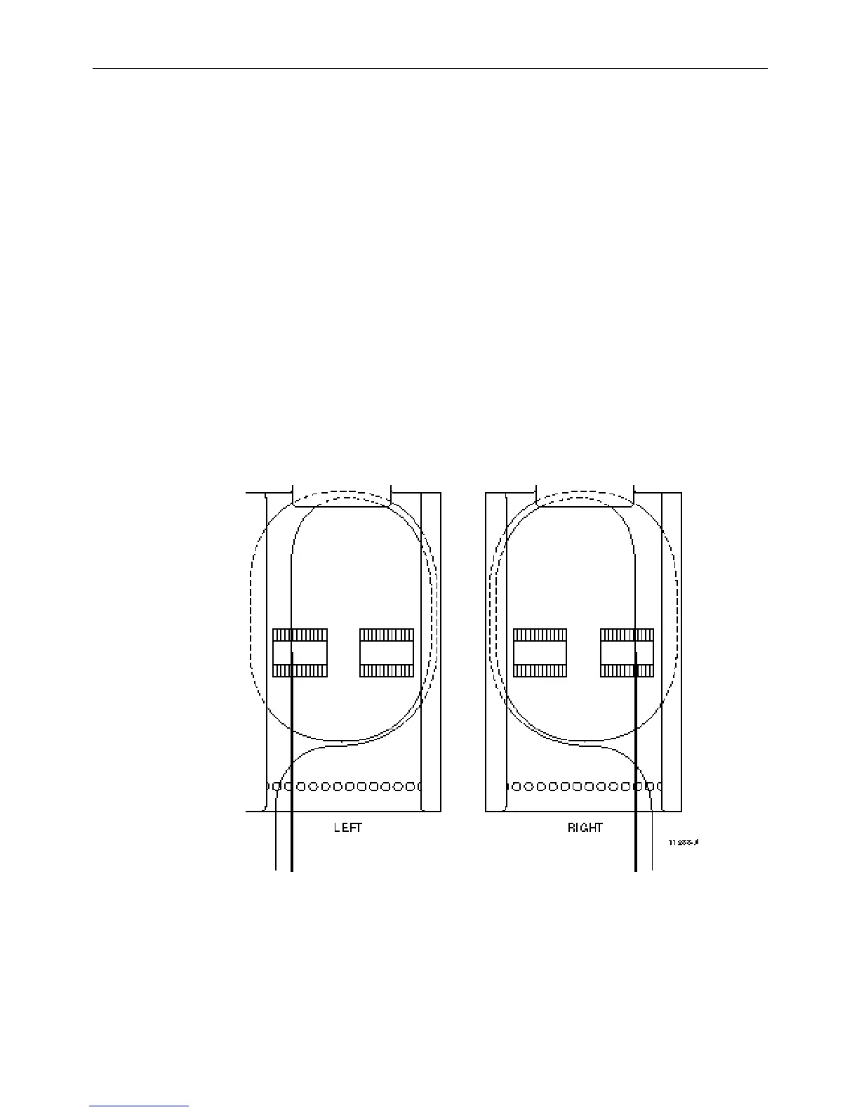
3. Route all fibers to the open end of the splice tray (witho
ut foldover tab), divided into left and
right groups corresponding to which splice chip they are going to be splice at. Figure 27
shows the recommended route within the splice tray using this
method. Tie down the fibers
with cord lacing using the tie-down holes (shown below) on the open side of the splice tray.
4. Remove the splice tray to a
working surface and complete the splice per local practice.
5. Repeat steps 2 to 4 above for any additional splice tray.
6. Place the splice trays back in the splice dec
k and place grommets on the radius limiters
above the splice trays to hold it in place within the splice deck (see Figure 26 insert).
Figure 27. Routing Fibers on a Splice Tray