ADCP-90-545 • Issue 4 • July 2016
Page 24
© 2016 CommScope. All Rights Reserved.
6. Route the fibers within the wall-mount box as shown in Figure 16, Figure 17, and
Figure 18. Tie the fibers down in the loc
ation shown using cord lacing.
Danger: Infrared radiation is invisible and can seriously damage the retina of the eye. Do not
look into the optical bulkhead of an operational transmitter, or into the launching (output) end
of an active fiber. A clean, protective cap or hood MUST be immediately placed over any
radiating bulkhead receptacle or optical fiber connector to avoid exposure to potentially
dangerous amounts of radiation. This practice also helps prevent contamination of connectors
and adapters.
7. Refer to subsection 3.4, Splicing for splicing instructions.
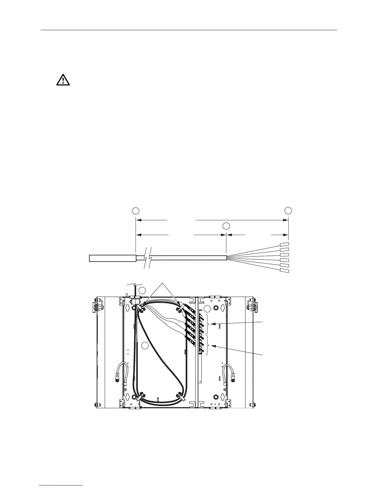
3.3.2 24-Fiber Termination/Splicing Wall-Mount Box
This unit can be used for either fiel
d termination or splicing. Figure 21 and Figure 22 show the
correct breakout for field termination when the
cable is routed in from the top. Figure 23 and
Figure 24 show the correct breakout for field termination when the cable is routed
in from the
bottom. Figure 25 shows the correct breakout for splicing.
IFC OR OSP
CABLE
A
B
C
SHEATH
67.0 IN.
(170.2 CM)
86.0 IN.
(218.4 CM)
19.0 IN.
(48.3 CM)
SUB-UNITS
FIBERS
CONNECTORS
24574-A
TOP 6 PAKS
(ROUTED FROM TOP)
A
B
C
RADIUS
LIMITERS
ROUTE TOP
THREE FIBERS
AROUND BOTH
RADIUS LIMITERS
ROUTE BOTTOM
THREE FIBERS
AROUND LEFT
RADIUS LIMITER
ONLY
Figure 21. Field Termination Breakout and Routing, 24-Fiber Wall-Mount Box (Top Entry, Top 6paks)