ADCP-90-545 • Issue 4 • July 2016
Page 14
© 2016 CommScope. All Rights Reserved.
2.4 Splicing
Use the following procedure for splicing.
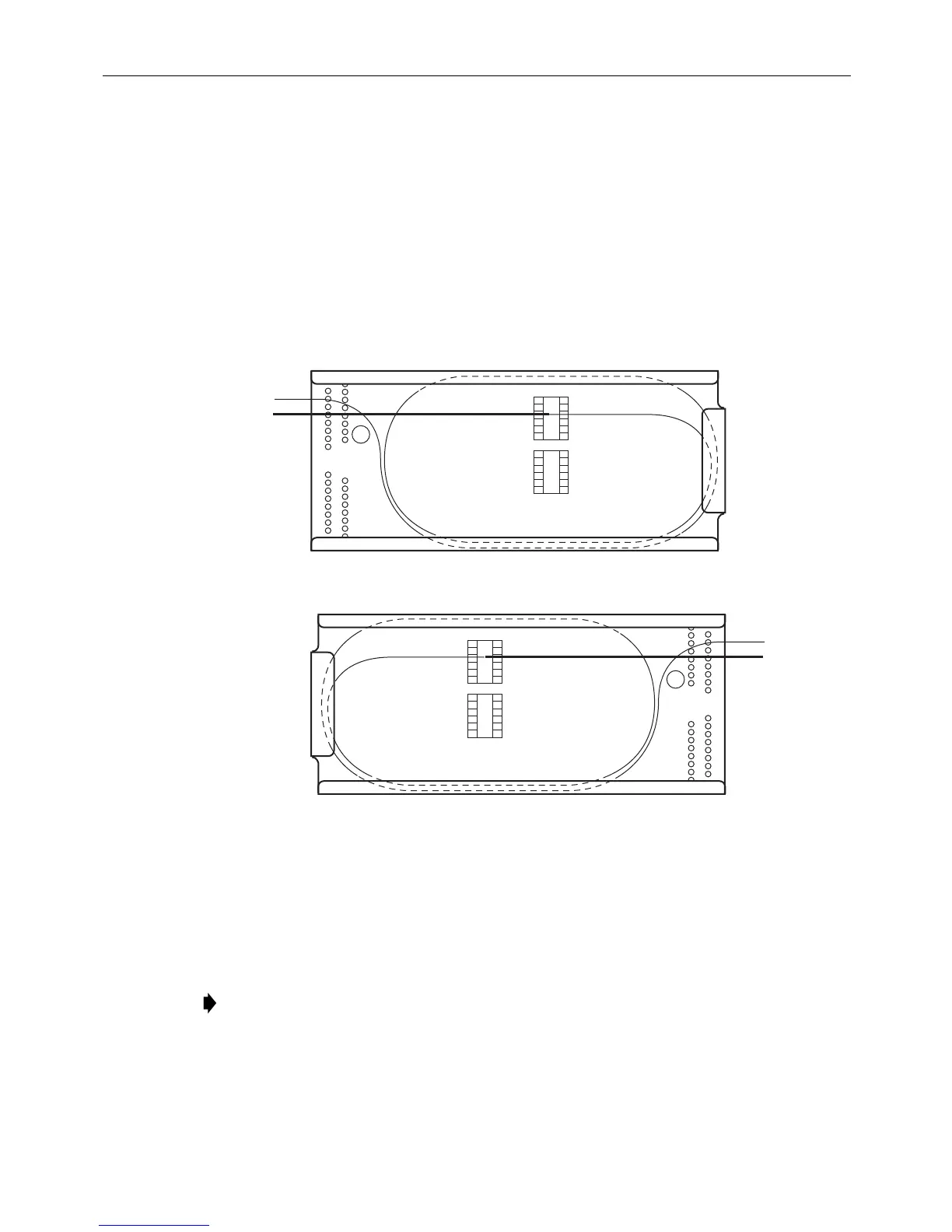
1. Place a splice tray in the splice drawer (if not already there).
2. Route the fiber into the splice tray on the same side as the
pigtail fiber that it is going to be
spliced to, as shown in Figure 10. Loop the fiber around twice in the splice tray.
3. Splice per local practice.
4. Tie down the fibers with cord lacing in
the C position shown in Figure 10. Refer also to
Figure 9 for correct routing.
LEFT
RIGHT
11419-A
C
C
Figure 10. Routing Fibers on a Splice Tray
3 WALL-MOUNT BOX INSTALLATION
3.1 Installing the Wall-Mount Chassis
Note: If using a cable clamp (as opposed to a compression fitting), install the cable clamp
prior to mounting the box on the wall.
FL1000 wall-mount boxes can be mounted directly to any wall, but CommScope recommends that
they be mounted, using the #12 woodscrews supplied with the unit, on a 3/4-inch thick plywood
panel that is attached to the wall in accordance with local fire code.