ADCP-90-545 • Issue 4 • July 2016
Page 15
© 2016 CommScope. All Rights Reserved.
Use the following procedure.
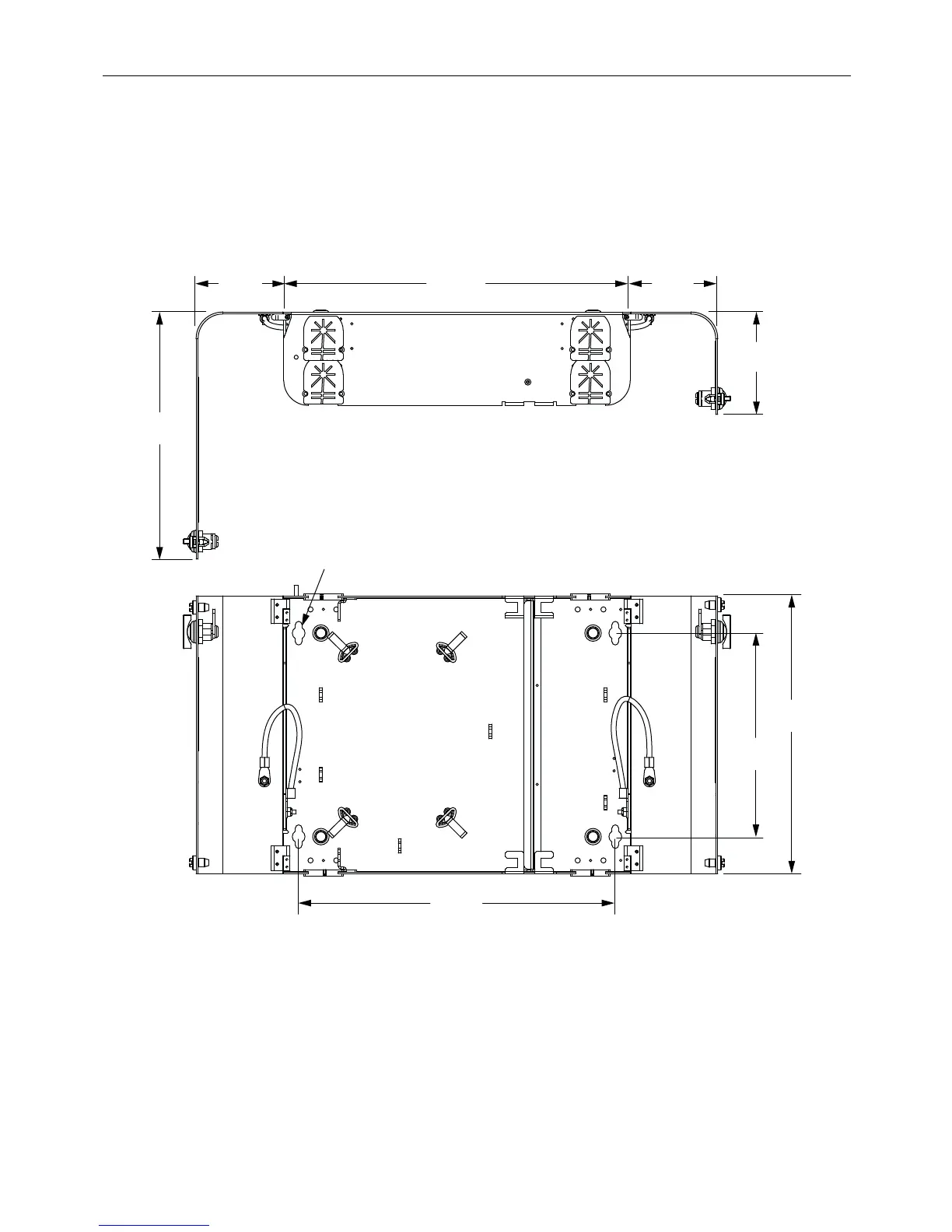
1. Make sure the location provides room for the door to swing out. See Figure 11 and Figure 12.
2. Position the box in its assigned
location and mark the mounting hole locations.
3. Fasten using the four #10-1.25 inch wood screws provided. See Figure 11 and Figure 12
for mounting hole location.
3.55 IN.
(9.0 CM)
10.07 IN.
(25.6 CM)
MOUNTING
HOLE
(4 PLACES)
12.80 IN.
(32.5 CM)
3.55 IN.
(9.0 CM)
4.22 IN.
(10.7 CM)
8.23 IN.
(20.9 CM)
14.00 IN.
(35.6 CM)
11.23 IN.
(28.5 CM)
TOP VIEW
FRONT VIEW
24562-A
Figure 11. 12-Fiber Wall-Mount Box Dimensions