ADCP-90-545 • Issue 4 • July 2016
Page 19
© 2016 CommScope. All Rights Reserved.
3.3 Installing Cables and Routing Fibers
The cable must be routed within the chassis in an orderly way that provides maximum
protection for the fibers and ease in future maintenance. For details refer to the following topics
for the three different types of wall-mount boxes. When routing and terminating fibers, observe
the following precaution to avoid potential eye damage.
Danger: Infrared radiation is invisible and can seriously damage the retina of the eye. Do not
look into the optical bulkhead of an operational transmitter, or into the launching (output) end
of an active fiber. A clean, protective cap or hood MUST be immediately placed over any
radiating bulkhead receptacle or optical fiber connector to avoid exposure to potentially
dangerous amounts of radiation. This practice also helps prevent contamination of connectors
and adapters.
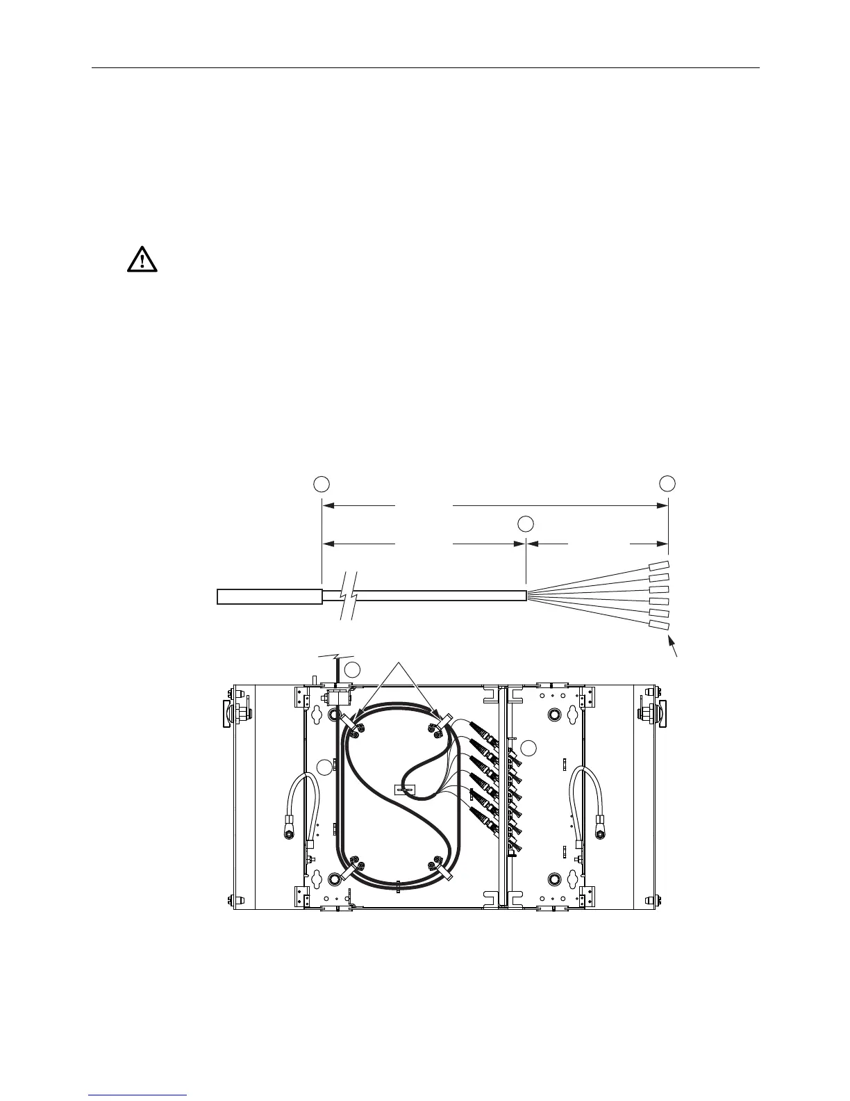
3.3.1 12-Fiber Termination/Splicing Wall-Mount Box
This unit can be used for either fiel
d termination or splicing. Figure 16 and Figure 17 show the
correct breakout for field termination. Figure 18 shows the correct breakout for
splicing.
IFC OR OSP
CABLE
A
B
C
SHEATH
45.0 IN.
(114.3 CM)
64.0 IN.
(162.6 CM)
19.0 IN.
(48.3 CM)
SUB-UNITS
FIBERS
CONNECTORS
24570-A
ROUTED
FROM TOP
C
B
A
RADIUS
LIMITERS
Figure 16. Field Termination Breakout and Routing, 12-Fiber Wall-Mount Box (Top Entry)