ADCP-90-545 • Issue 4 • July 2016
Page 10
© 2016 CommScope. All Rights Reserved.
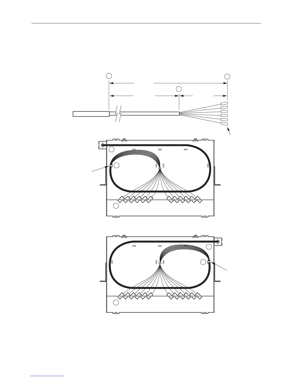
2.3.2 24-Fiber Termination Rack Mount Panel
Figure 7 shows cable routing options and breakout dimensions for the 24-fiber termination rack-
mount panel. The cable can enter from above or below
the chassis and from the left or right side.
11245-E
CABLE ENTRY
FROM LEFT
TIE DOWN
USING CORD
LACING
TIE DOWN
USING CORD
LACING
CABLE ENTRY
FROM RIGHT
IFC OR OSP
CABLE
A
A
A
B
C
C
B
C
SHEATH
57.0 IN.
(144.78 CM)
41.0 IN.
(104.14 CM)
16.0 IN.
(40.64 CM)
SUB-UNITS
FIBERS
CONNECTORS
B
Figure 7. Cable Breakout for 24-Fiber Panel
Use the following procedure to install a cable in the 24-fiber termination rack-mount panel.