ComNav 2001 Autopilot System
P/N 29010017 V1.0 - 52-
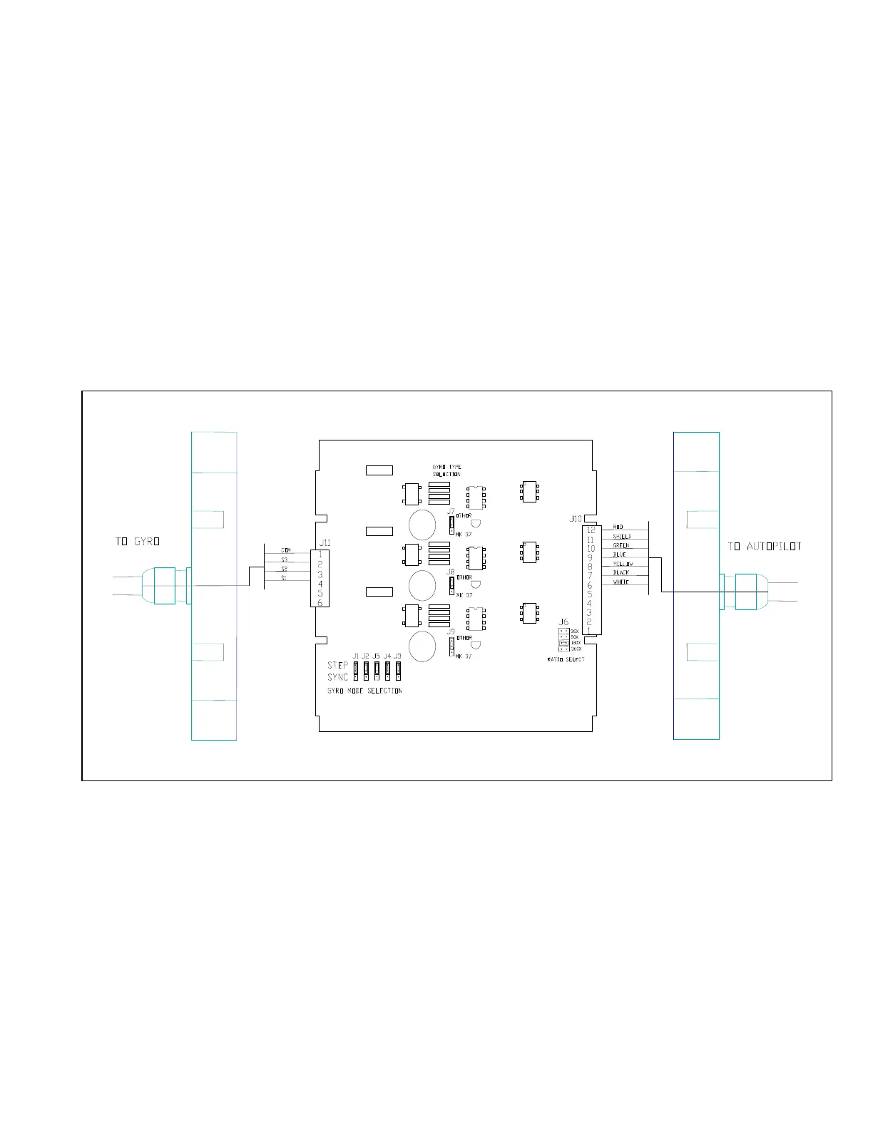
Set the Synchro/Step selectors J1-J5 to the
appropriate position to accommodate the
Gyrocompass. If the gyrocompass has a
SYNCHRO output, they must all be in the
SYNCHRO position. If the gyrocompass hasa
STEP output, they must all be in the STEP
position.
Set J6 to the Gyro gear ratio. The autopilot
MUST have software version 02.06 (01.15) or
higher to use the 36:1 ratio. If the gyrocompass
has a 6 Step/Degree output (very common) select
the 180X ratio.
Plug the Interface output cable into the OPTION
receptacle on the rear of the autopilot. The
Interface will automatically set itself to the output
voltage of the Gyro Transmitter.
With some older Sperry MK37 gyrocompasses
(ie. MOD 0 or MOD 1) problems with the
regulation of the 70VDC positive common can
interfere with the correct operation of the
interface. This is indicated by repeated GC.Er
alarms on the autopilot display. To correct this
problem, turn off the output from the
gyrocompass, move each of the J7, J8 and J9
jumpers so they are on one pin only and retest.
This should solve the problem.
Figure 13 - Gyro Compass Interface