ComNav 2001 Autopilot System
P/N 29010017 V1.0 - 21-
INSTALLATION INSTRUCTIONS
RUDDER FOLLOWER
The rudder follower is used to transmit the
position of the rudder back to the autopilot. It
should be connected to whatever part of the
steering system the autopilot controls. Normally,
this will be the vessels rudder.
However, if the vessel has 2 stage steering, where
the autopilot drives a control or servo ram, the
rudder follower should be mounted to the servo
ram rather than to the rudder. If the rudder
follower is connected directly to the rudder in this
case, uncontrollable hunting of the rudder will
result.
Normally the rudder follower is mounted in the
stern of the vessel, close to the rudder post. A
mounting base may have to be fabricated to
position the rudder follower properly. Mount the
rudder follower in a location where the possibility
of damage from any equipment stowed in the area
is minimized.
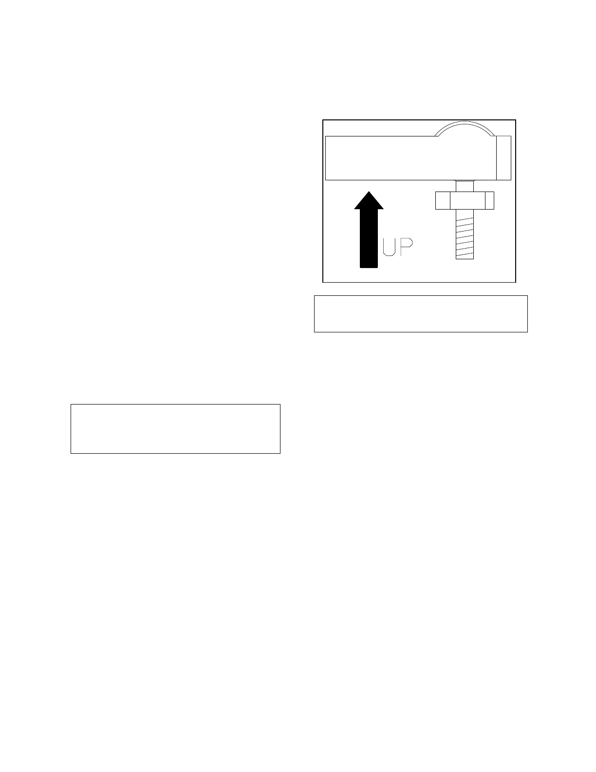
Mount the rudder post arm on the rudder post
using a stainless steel band clamp (not supplied).
Bolt the ball joint to the hole in the rudder post
arm corresponding to the diameter of the rudder
post in inches, making sure the ball is facing
upwards. Mount the rudder follower so that the
rudder follower arm is the same height as the
rudder post arm. The rudder follower is centred
when the arm is directly above the cable gland.
See Figure 4 and 5 for alignment details.
If a Heavy Duty rudder follower was supplied
Mount the rudder follower so that the top of the
vessel's tiller arm is 1 - 3/4 inches lower than the
top of the rudder follower arm. On the centerline
of the vessel's tiller arm, and within 3 to 5 inches
from the centre of the rudder post, either:
- drill and tap a hole 1/4-20 or,
- drill a clearance hole for a 1/4 inch bolt if
enough of the threads of the supplied ball joint
will come through the tiller arm to permit the
supplied nut to be threaded onto it. The rudder
follower is centred when the arm is pointing away
from the cable gland and is directly over the
stainless rivet in the top cover. See Figure 5 for
alignment details.
If a Medium Duty rudder follower was
supplied
Figure 4 - Correct Linkage Orientation