ComNav 2001 Autopilot System
P/N 29010017 V1.0 - 58-
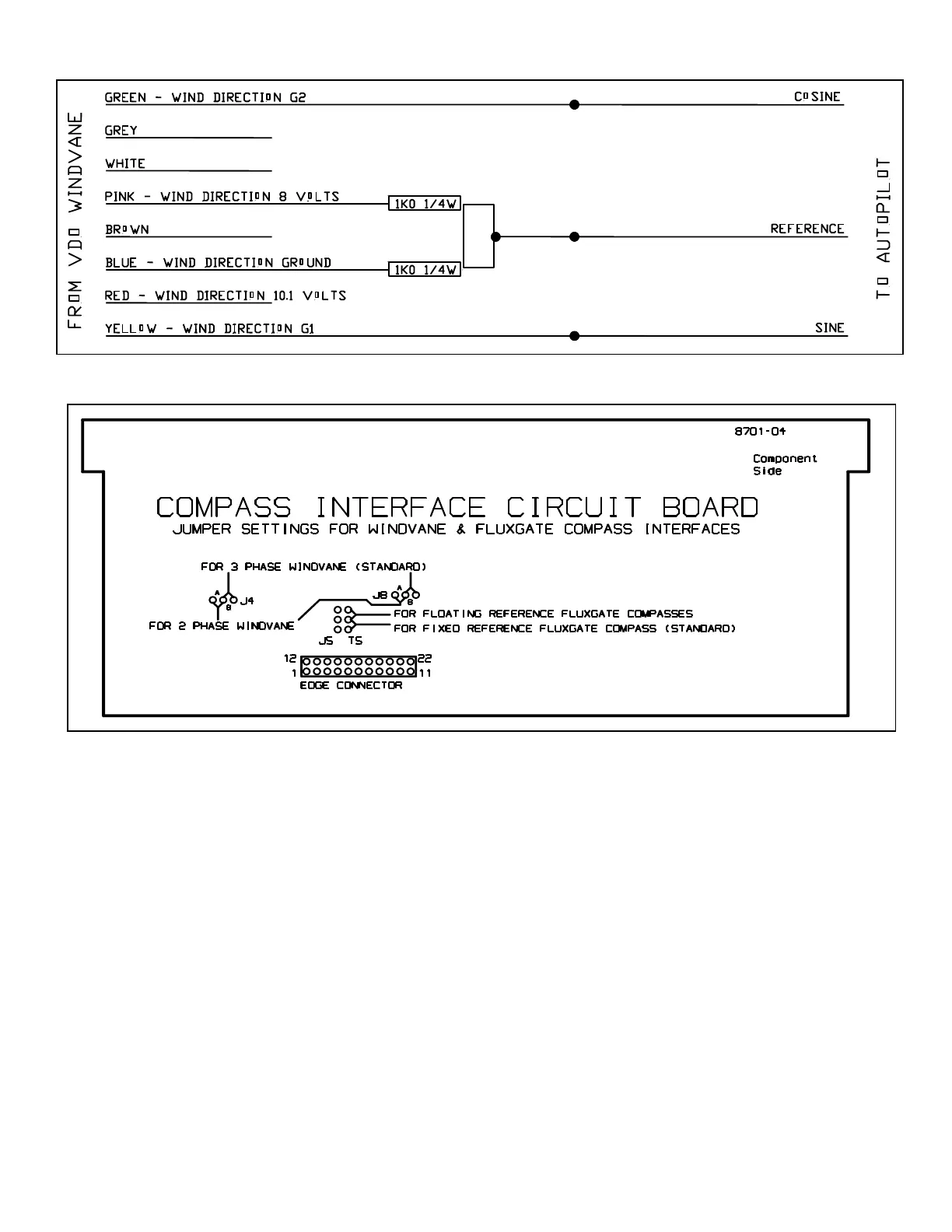
The Sine and Cosine wires from the autopilot
should be hooked in parallel with the YELLOW
and GREEN wires from the masthead unit. The
unused wires in the cable from the autopilot
should be cut off to avoid the possibility of short
circuits. Turn on the wind instrument, place the
autopilot master select switch in the STANDBY
position, and press the WIND ON/SET key. If
the reading on the autopilot display is increasing
when the actual wind angle is decreasing, reverse
the Sine and Cosine connections from the
autopilot. Press and hold the WIND ON/SET
key and press either the up or down ARROW
key until the reading on the autopilot display is
the same as the actual wind angle.
OTHER WIND INSTRUMENTS
As mentioned earlier, the autopilot is compatible
with wind vanes which have a three phase DC
output from the masthead unit. By moving a pair
of jumpers on the Compass Interface Circuit
Board (which should only be done by your
dealer), the autopilot can also work with a 2
phase
(sine/cosine) output with up to a 6V reference.
Less expensive windvanes which use a simple
potentiometer in the masthead unit and have a
dead zone, typically at head to wind, are not
compatible with the autopilot.
Figure 15 - COMPASS INTERFACE PCB JUMPER SETTINGS
Figure 14 - VDO WINDVANE HOOKUP